PARAMETRIC · 3D · STEP
Bevel Gear Generator
Enter module, teeth, face width, bore diameter, and output gear selection to generate a STEP file for a bevel gear.
Pressure Angle
20°
Backlash
None
Axes Angle
90°
🔍
View 3D Preview First
HOW-TO How to Generate a Bevel Gear STEP File +
- Enter the module, number of teeth, face width, bore diameter, and output gear
- Calculated values update in real time as parameters change
- Click "Download STEP File" or "Preview STEP Model"
- If you selected "Download STEP File", the STEP file will be saved automatically
- If you selected "Preview STEP Model", check the 3D model, then click "Download STEP File" manually
SAMPLE
STATIC · DEFAULT-VALUE MODEL
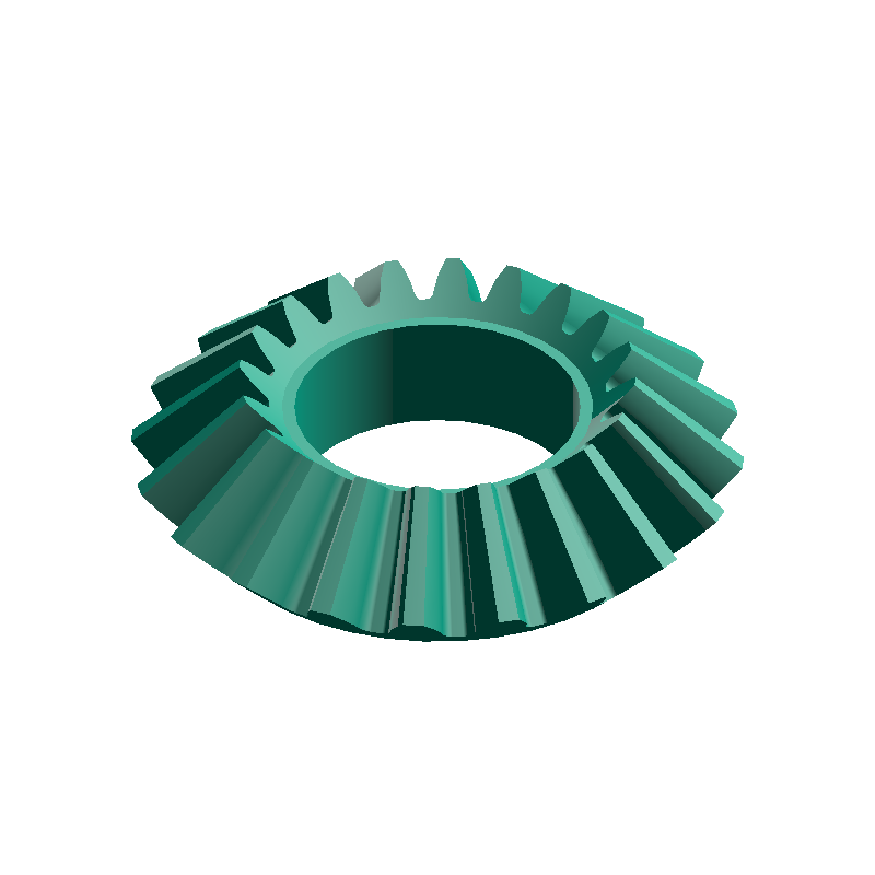
CALCULATED · SPEC
AUTO-COMPUTED
r₀
28.28mm
Reference Sphere Radius (r0)
γ₁
45.00deg
Pitch Cone Angle (γp1)
γ₂
45.00deg
Pitch Cone Angle (γp2)
d₁
40.00mm
Outer Pitch Circle Diameter (d1)
d₂
40.00mm
Outer Pitch Circle Diameter (d2)
SPONSORED
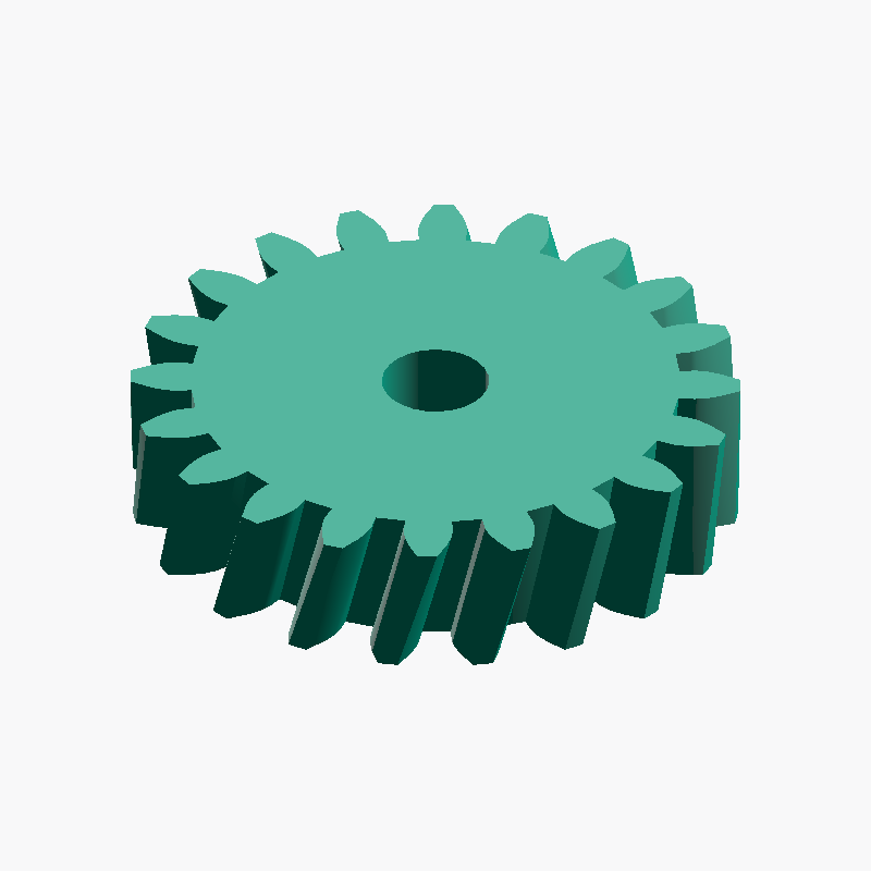
- ⚙️ Gear Ratio Calculator Calculate gear ratio, output speed, and torque from driver and driven tooth counts (multi-stage)
- ↔️ Spur Gear Center Distance Calculator Calculate spur gear center distance and key dimensions from the module and two gear tooth counts
- ➰ V-Belt Length & Center Distance Calculator Calculate the recommended belt designation, actual center distance, wrap angle and belt speed from the belt type and effective pulley diameters
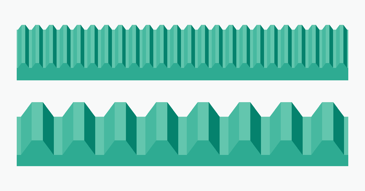
Gear Module Explained — How to Choose the Right Module for 3D Printing and DIY
2026-05-27
PARAMETERS
Enter Dimensions
ABOUT · STEP
The STEP file (.step / .stp) is a standard 3D CAD format that retains dimensional and topology data. Compatible with major CAD software including Fusion 360, SolidWorks, and FreeCAD.
- Full-scale solid (mm units)
- Editable dimensions and post-processing in CAD
- Convertible with a slicer for 3D printing
FEEDBACK
BUG · REQUEST
0 / 500