Zahnradmodul erklärt — Das richtige Modul für 3D-Druck und Hobbyprojekte wählen
Das Modul eines Zahnrads (Formelzeichen m) ist eine Normgröße in Millimetern, die die Größe der Zähne beschreibt. Die mit Abstand wichtigste Regel lautet: Zwei Räder können nur dann miteinander kämmen, wenn sie dasselbe Modul haben. Wer Zahnräder nur nach Zähnezahl oder Außendurchmesser auswählt, erhält Räder, die schlicht nicht ineinandergreifen. Dieser Leitfaden erklärt das Grundkonzept des Moduls, die Regel des Eingriffs, den Unterschied zwischen Modul und Zähnezahl sowie die Wahl des Moduls für 3D-Druck und Hobbyprojekte — direkt verknüpft mit den Zahnrad-Generatoren von meta-matic.
Was ist das Modul?
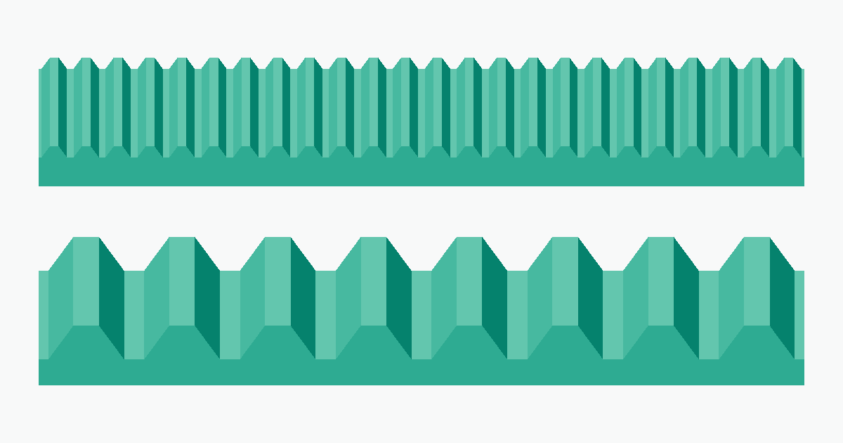
Das Modul ist die Größennorm der Zahnradzähne, festgelegt in JIS B 1701-1 / ISO 53. Vereinfacht gesagt drückt es „wie groß die Zähne sind" als einzelne Kennzahl in mm aus. Ein Rad mit m = 1 hat im Vergleich zu einem Rad mit m = 2 die halbe Zahngröße, halbe Zahnhöhe und halbe Teilung.
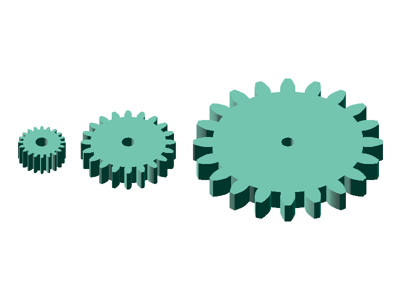
Das Modul bestimmt zugleich die Teilung — also den Abstand von Zahn zu Zahn, gemessen entlang des Teilkreises. Aus Modul und Zähnezahl ergibt sich der Teilkreisdurchmesser (der Bezugsdurchmesser des Rades) nach folgender Formel.
d = m × z (Teilkreisdurchmesser = Modul × Zähnezahl)
3,14 mm (= π × m). Bei Modul 2 ist es das Doppelte, also 6,28 mm. Messen Sie den Zahn-zu-Zahn-Abstand an einem beliebigen Standardrad in Ihrer Werkstatt und Sie können dessen Modul abschätzen.Warum gibt es überhaupt eine solche Norm? — Weil Zahnräder Maschinenelemente sind, die rund um Austauschbarkeit entworfen werden. Da das Modul breit genormt ist, lassen sich Räder verschiedener Hersteller paaren oder ein verschlissenes Rad gegen ein anderes Standardteil tauschen. Bei Schrauben und Lagern gilt dieselbe Logik: Das Modul ist beim Zahnrad das, was M3 / M5 bei den Gewindenormen ist.
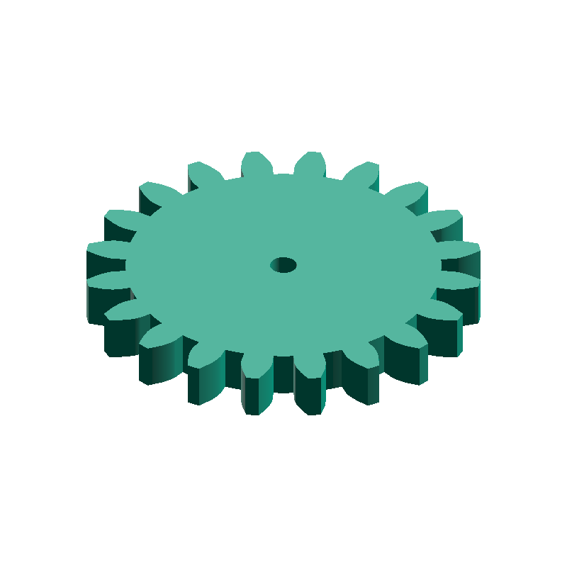
Zahnräder mit unterschiedlichem Modul greifen nicht ineinander
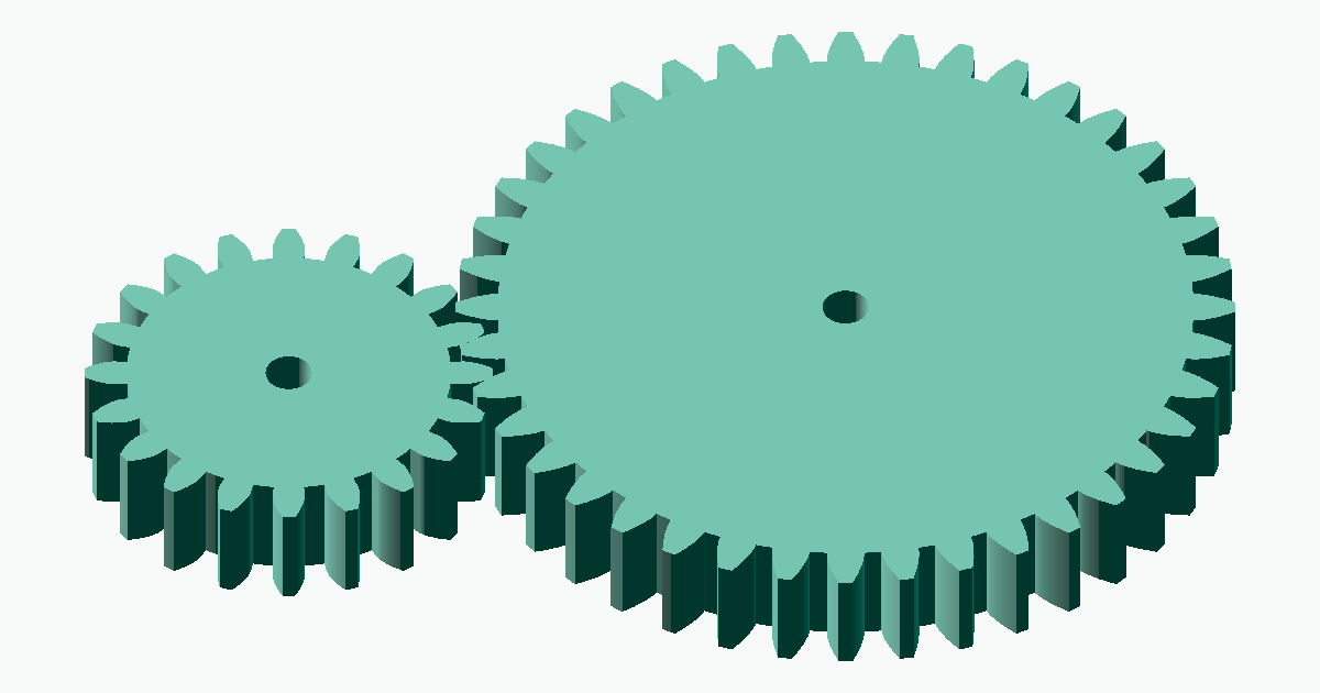
Die wichtigste Regel der Zahnradauslegung lautet, dass zwei ineinandergreifende Räder dasselbe Modul haben müssen. Stimmen die Module nicht überein, passen auch die Zahnteilungen nicht zusammen, die Zahnspitzen stoßen aufeinander und die Räder können sich nicht drehen. Selbst wenn Zähnezahlen oder Außendurchmesser ähnlich aussehen, greifen Räder mit unterschiedlichem Modul physisch nicht ineinander.
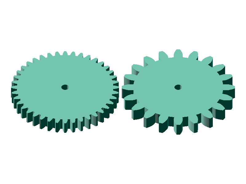
Räder, die nicht ineinandergreifen, verraten sich häufig durch die folgenden Symptome. Bei Problemen sollte zuerst eine Modul-Fehlpaarung vermutet werden.
- Kein Eingriff — Die Zähne greifen gar nicht und nur ein Rad dreht sich
- Berührung nur an den Spitzen — Beim Zusammendrücken hakt es, beim Drehen rutscht es wieder auseinander
- Kurzes Greifen, dann Zahnüberspringen — Sie greifen für einige Zähne ineinander und schnappen dann mit einem „Klick" heraus
- Geräusche und Vibrationen — Eine ungleiche Eingriffsteilung erzeugt ein periodisches Geräusch
- Abgebrochene Zahnspitzen — Erzwungenes Drehen bricht am Ende den schwächeren Zahnkopf ab
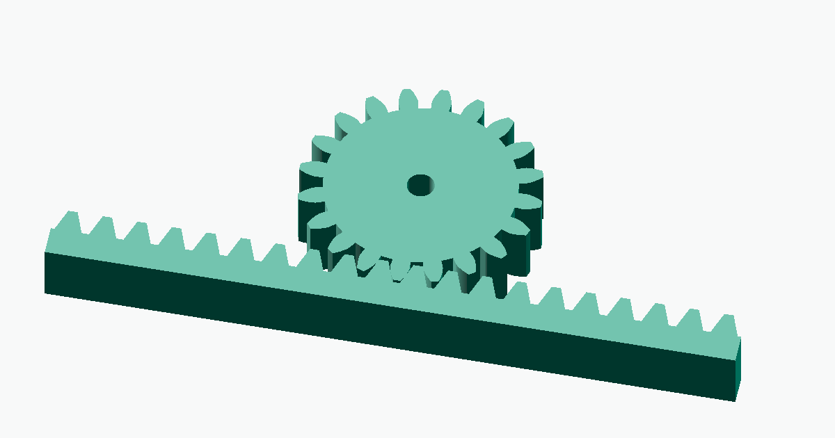
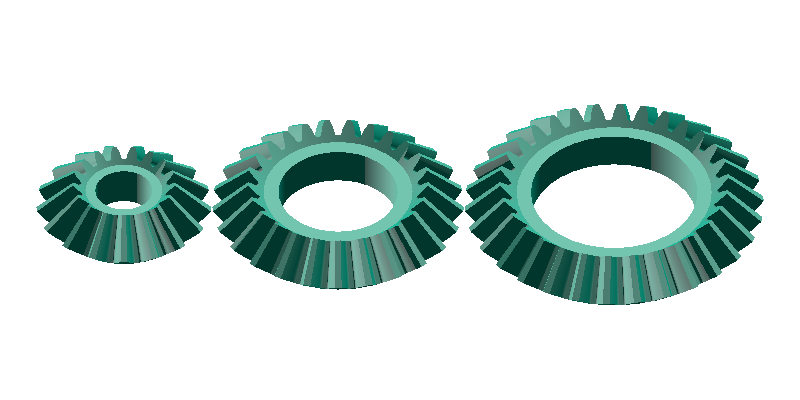
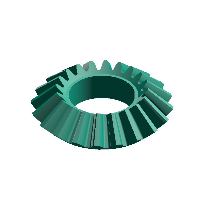
Umgekehrt formuliert: Gleiches Modul ist die Grundvoraussetzung für den Zahneingriff. Zahnstange und Ritzel (Stirnrad + lineare Zahnstange), Kegelradpaare, Schnecke und Schneckenrad — jede unterstützte Kombination muss mit demselben Modul ausgelegt sein. Beachten Sie: Kombinationen mit unterschiedlichen Wellenanordnungen (z. B. Stirnrad mit Kegelrad oder Stirnrad mit Schneckenrad) greifen auch bei gleichem Modul nicht ohne Weiteres ineinander.
Streng genommen muss zusätzlich der Eingriffswinkel (der Winkel der Zahnform, typisch 20°) übereinstimmen, aber im Hobby- und 3D-Druck-Bereich ist das verbreitete 20°-Profil faktisch der Standard und auch die meta-matic-Generatoren verwenden es. Nur bei der Paarung mit Standardrädern empfiehlt sich eine Kontrolle des Eingriffswinkels.
Modul vs. Zähnezahl
Modul und Zähnezahl werden häufig verwechselt, erfüllen aber unterschiedliche Aufgaben. Das Modul legt fest, „wie groß ein einzelner Zahn ist", die Zähnezahl, „in wie viele Teile der Umfang aufgeteilt wird". Beide lassen sich unabhängig wählen, beeinflussen aber über den Teilkreisdurchmesser d = m × z die Gesamtgröße des Rades.
- Modul ändern → ändert die Größe eines einzelnen Zahns (beeinflusst Festigkeit und Eingriffsgenauigkeit)
- Zähnezahl ändern → ändert die Aufteilung des Umfangs (beeinflusst Übersetzungsverhältnis und Drehauflösung)
- Beides beeinflusst über den Teilkreisdurchmesser
d = m × zdie Gesamtgröße des Rades
Möchten Sie beispielsweise ein „Ritzel mit 40 mm Durchmesser" entwerfen, ergeben m = 1 × z = 40, m = 2 × z = 20 oder m = 4 × z = 10 deutlich unterschiedliche Zahngrößen. Die Zähnezahl beeinflusst vor allem das Übersetzungsverhältnis und die Drehauflösung; die Drehzahl selbst ergibt sich aus dem Zähnezahlverhältnis zum Gegenrad. Ein Ritzel mit niedriger Zähnezahl erleichtert kompakte Mechaniken, und in Kombination mit einem zähnereichen Großrad lässt sich ein hohes Übersetzungsverhältnis erzielen.
Modulwahl nach Einsatzfall
Wählen Sie das Modul entlang von drei Achsen: Baugröße, Festigkeit und 3D-Druck-Tauglichkeit. Für industrielle Anwendungen legt JIS eine genormte Modulreihe fest (0,5 / 0,8 / 1,0 / 1,25 / 1,5 / 2,0 / 2,5 / 3,0 / 4,0 / 5,0 ...); für Hobbyprojekte und 3D-Druck müssen Sie sich nicht an die Normreihe halten — außer bei der Paarung mit Standardrädern.
| Modul | Anwendungsbereich | 3D-Druck-Tauglichkeit | Typische Einsätze |
|---|---|---|---|
| 0,5 | Feinwerktechnik / Kleinmodelle | Zahnspitzen brechen — nicht empfehlenswert | Uhrwerke, Präzisionsrobotik, mit SLA tauglich |
| 1,0 | Kleine Mechaniken | Grenzwertig nutzbar | Desktop-Roboter, kleine Getriebe |
| 1,5 – 2,0 | Optimalbereich für Hobbyprojekte | Am besten druckbar | Allgemeine Hobbyprojekte, CNC, 3D-Drucker-Teile, Lehrkits |
| 3,0 | Hochmoment-Anwendungen | Reichlich Reserve beim Druck | Untersetzungsgetriebe, Hochmoment-Mechaniken, Holzspielzeug |
| 5,0 und mehr | Schwermaschinen-Bereich | Überdimensioniert für den Druck | Industriemaschinen, Baumaschinen, große Vorrichtungen |
π × m / 2 ≒ 1,5708 × m, also bei m = 0,5 rund 0,78 mm. Die eigentliche Zahnspitze ist aufgrund der Evolventenform noch dünner, sodass ein FDM-Drucker mit 0,4-mm-Düse nicht einmal zwei Extrusionsbahnen quer darüber legen kann. Für Füllung bleibt kein Platz, und die schräge Schichtung zerbröselt die Zahnspitzen. Für FDM-3D-Drucker wird m = 1,5 oder größer dringend empfohlen (mit SLA oder DLP ist m = 0,5 in der Praxis machbar).Bei der Paarung mit Standardrädern stets das Modul des vorhandenen Produkts übernehmen. Eine häufige Ursache für Eingriffsprobleme ist die Kombination eines Sonderrads mit einem Standardritzel bei unterschiedlichem Modul.
Erzeugung auf meta-matic
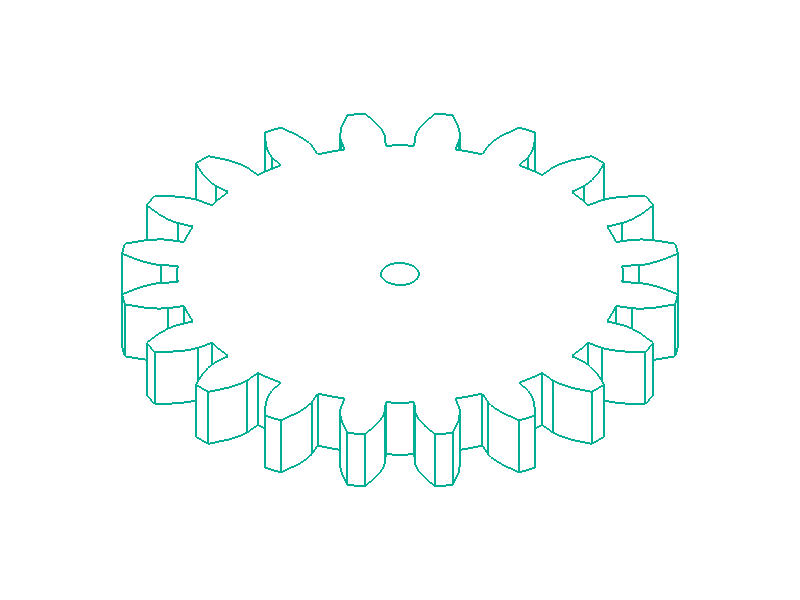
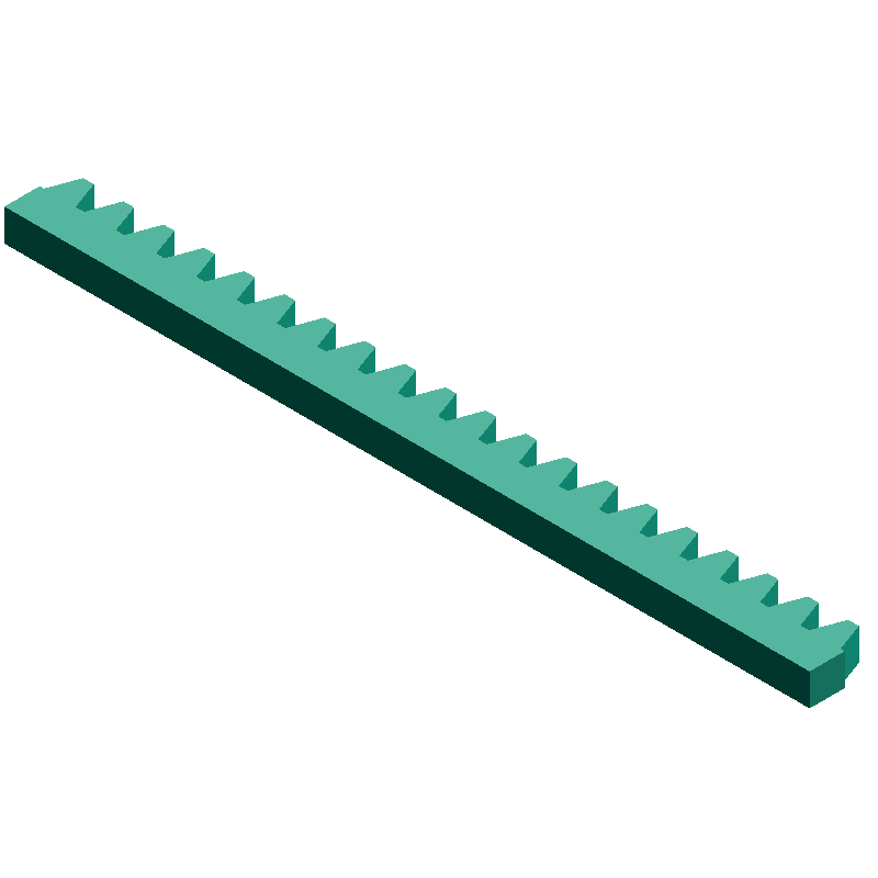
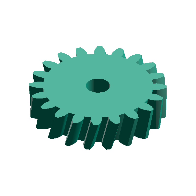
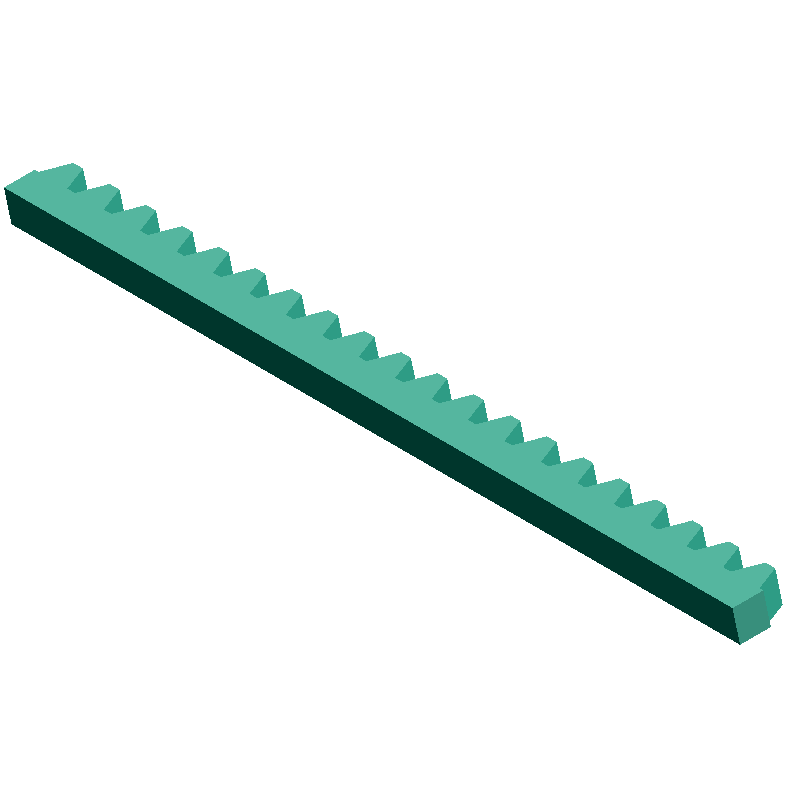
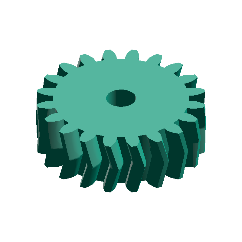
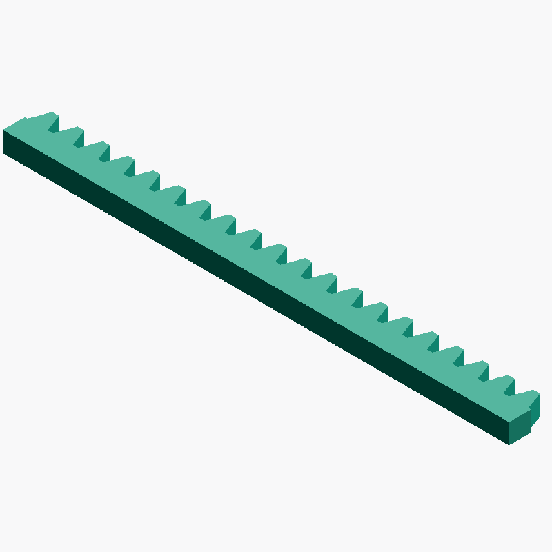
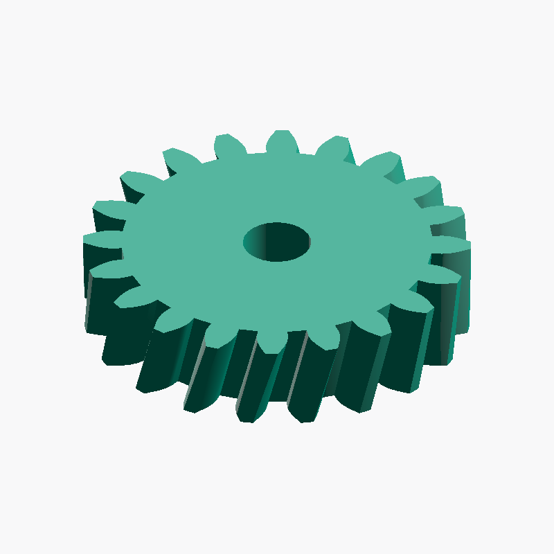
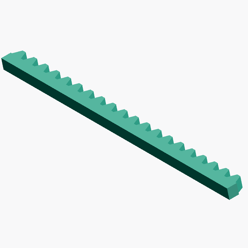
Wenn Sie sich auf ein Modul festgelegt haben, können Sie das zugehörige 3D-Modell auf meta-matic erzeugen. Entscheidend ist, dass alle Räder eines Eingriffssets dasselbe Modul tragen. Beim Entwurf eines Zahnstange-Ritzel-Mechanismus müssen z. B. Stirnrad und Zahnstange mit demselben Modulwert erzeugt werden.
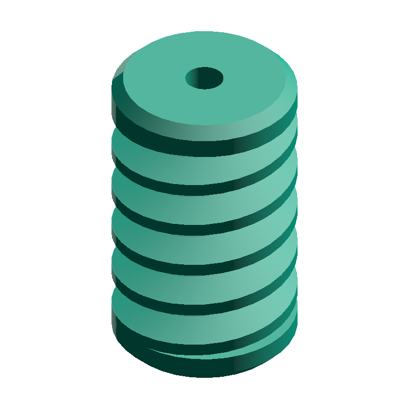
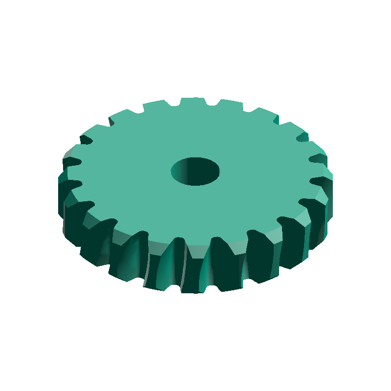
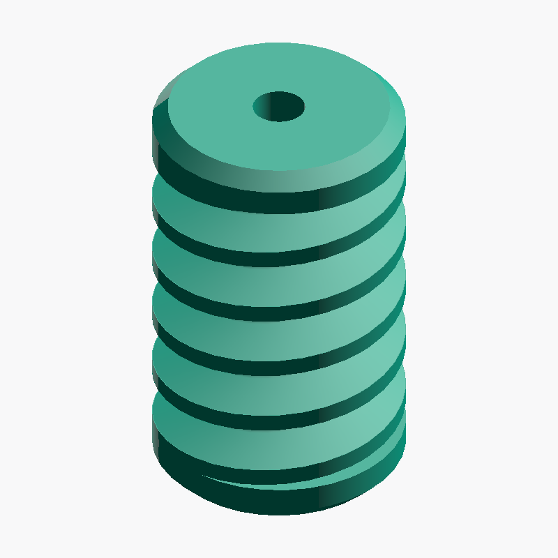
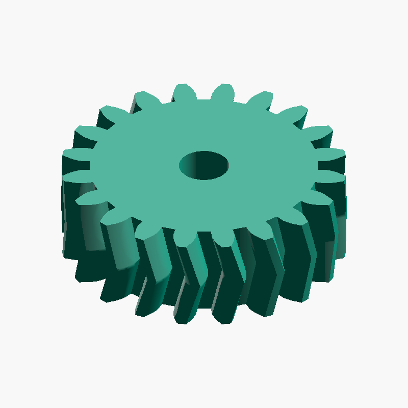
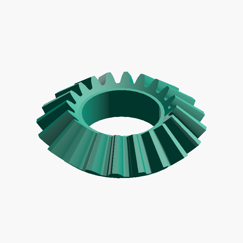
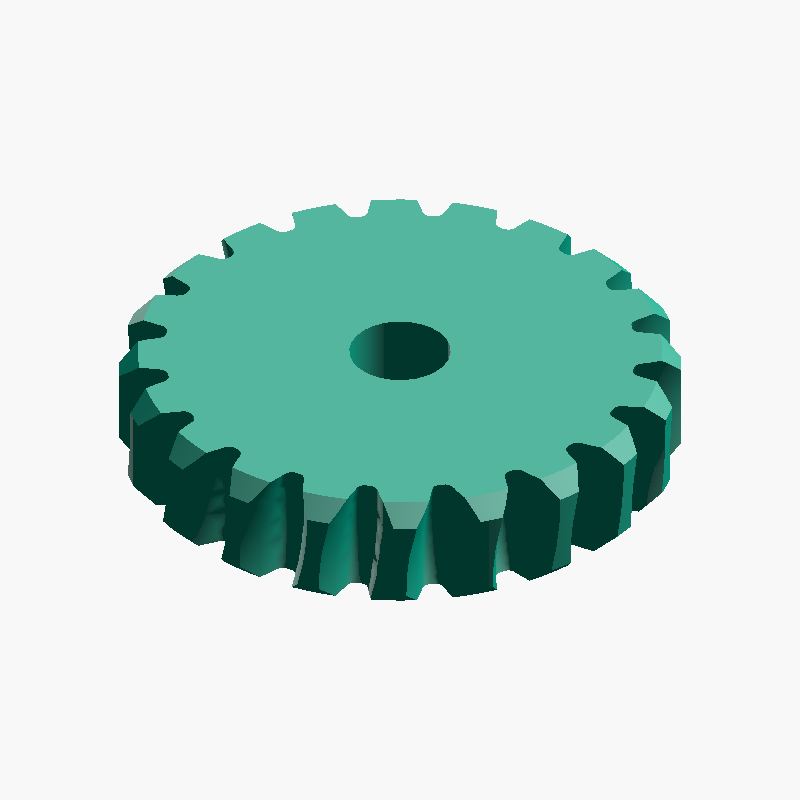
Auf allgemeinen 3D-Modell-Plattformen finden sich gängige Stirnräder, doch Kegelräder oder Schneckenräder mit beliebigem Modul und beliebiger Zähnezahl zu finden, ist schwierig — meist müssen sie im CAD von Grund auf neu konstruiert werden. meta-matic ermöglicht es, Stirn-, Zahnstangen-, Kegel-, Schnecken- und Schrägverzahnungen mit demselben Modul zu erzeugen, sodass ineinandergreifende Paare oder Sets ohne Mehraufwand entstehen.
Häufig gestellte Fragen
QWas passiert, wenn ich Räder mit unterschiedlichem Modul kombiniere?
QWorin liegt der Unterschied zwischen Modul und DP (Diametral Pitch)?
m = 25,4 / DP. Beispielsweise entspricht DP = 24 etwa m ≈ 1,058. In US-Zahnradkatalogen dominiert die DP-Notation; beim Mischen mit metrischen Rädern ist Vorsicht geboten.QSind kleinere Module leistungsfähiger?
QWelches Modul ist am besten für ein 3D-gedrucktes Zahnrad?
m = 1,5 – 2,0 am besten drucken. Bei m = 1 und kleiner werden die Zahnspitzen so dünn, dass das Schicht-Kollabieren spürbar zunimmt. SLA oder DLP schaffen m = 0,5 in der Praxis; für PLA- oder PETG-Filament ist ein Einstieg um m = 2 jedoch am sichersten.
- ↔️ Stirnrad-Achsabstand-Rechner Berechnet Achsabstand und wichtige Maße von Stirnrädern aus Modul und zwei Zähnezahlen
- ⚙️ Übersetzungsrechner Berechnet Übersetzungsverhältnis, Ausgangsdrehzahl und Drehmoment aus Antriebs- und Abtriebszähnezahl (mehrstufig)
- 📏 Schrittmotor-Steps/mm-Rechner Berechnet Steps/mm und Verfahrweg aus Schrittwinkel, Mikroschrittauflösung und Antriebsart