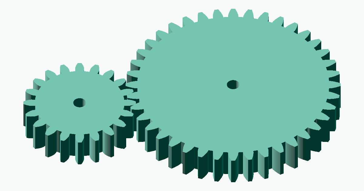
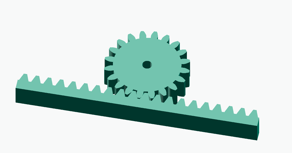
齿轮模数是表示齿大小的标准值,只有模数相同的两个齿轮才能正确啮合。本文围绕 meta-matic 的齿轮生成功能,介绍模数的基本概念、啮合法则、与齿数的区别,以及面向不同用途(包括 3D 打印)的推荐模数值。
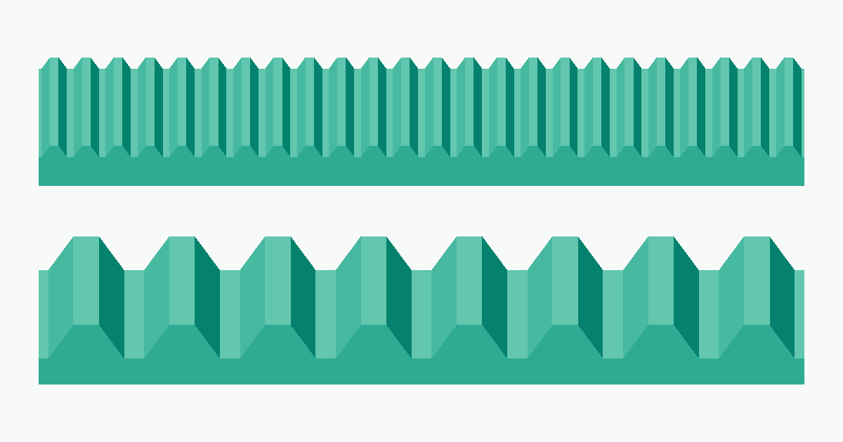
齿轮模数详解 — 如何为 3D 打印和 DIY 选择合适的模数
The module of a gear (symbol m) is a standard value in millimeters that represents the size of the teeth. The single most important rule is that two gears only mesh if they share the same module. Selecting a gear by tooth count or outer diameter alone leads to gears that simply will not engage. This guide explains the basic concept of the module, the mesh-engagement rule, the difference between module and tooth count, and how to choose a module for 3D printing / DIY — all tied to the gear generators on meta-matic.
What is the module?
The module is the size standard for gear teeth, defined by JIS B 1701-1 / ISO 53. Put simply, it expresses "how large the teeth are" as a single number, with units in mm. A gear with m = 1 has half the tooth size, height, and pitch of a gear with m = 2.
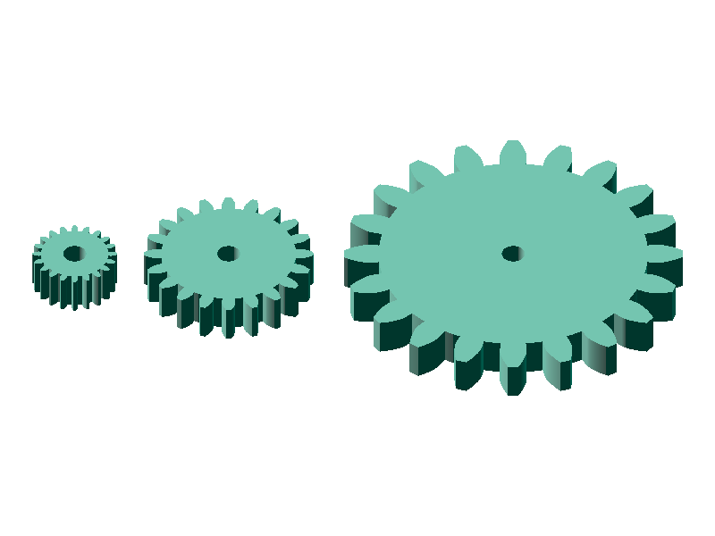
The module also determines the tooth pitch — the distance from one tooth to the next measured along the pitch circle. From the module and the tooth count, you can compute the pitch circle diameter (the reference diameter of the gear) with the following formula.
d = m × z (pitch circle diameter = module × tooth count)
3.14 mm (= π × m). For module 2 it is double that, 6.28 mm. Measure the tooth-to-tooth distance on any off-the-shelf gear you have on hand and you can estimate its module.Why does such a standard exist? — Because gears are mechanical elements designed around interchangeability. With the module widely standardized, you can pair gears from different manufacturers or swap a worn gear for another off-the-shelf part. The same logic applies to screws and bearings: the module is to gears what M3 / M5 are to thread standards.
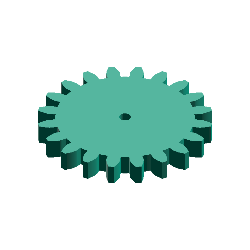
Different modules will not mesh
The most important rule in gear design is that two meshing gears must share the same module. If the modules differ, the tooth-to-tooth pitch will not line up and the tooth tips collide, so the gears cannot rotate. Even when the tooth counts or outer diameters look similar, gears with different modules will physically not engage.
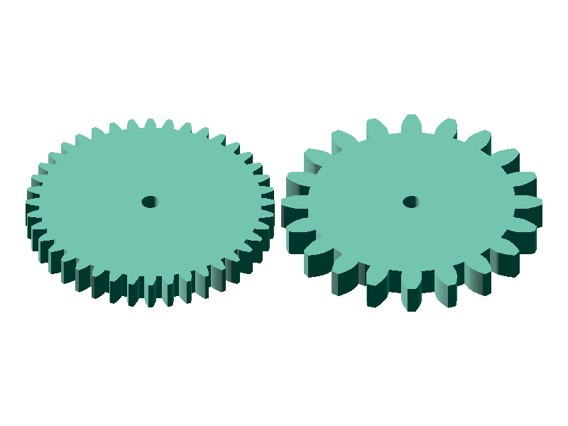
Gears that fail to mesh tend to reveal themselves through the following symptoms. When something goes wrong, suspect a module mismatch first.
- Free-spinning — The teeth do not catch at all and only one gear rotates
- Tip-only contact — They snag when pressed together but slip apart once you try to turn them
- Brief mesh then tooth-jump — They engage for a few teeth before snapping out with a "click"
- Noise and vibration — Mismatched mesh pitch produces a periodic noise
- Chipped tooth tips — Forced rotation eventually breaks the weaker tip
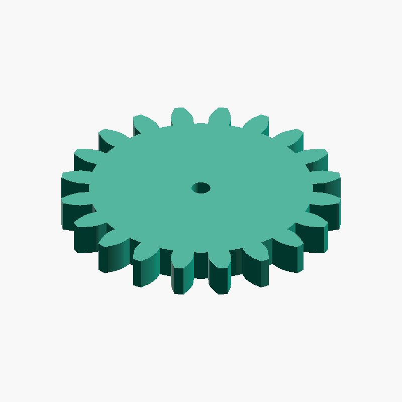
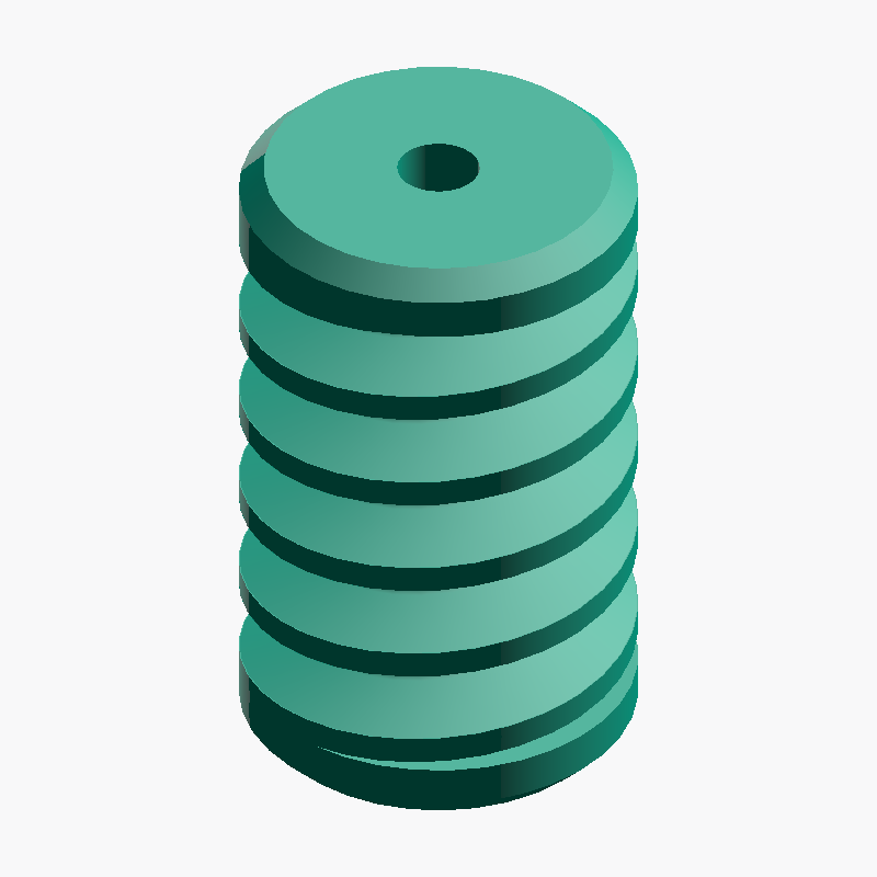
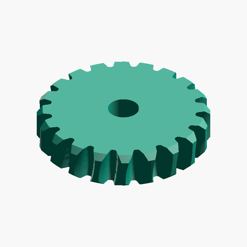
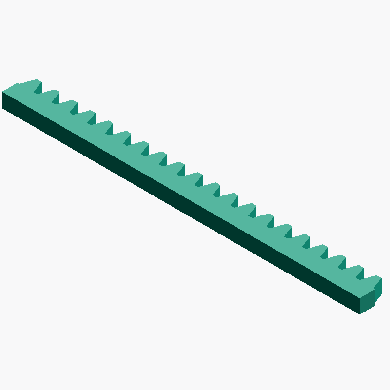
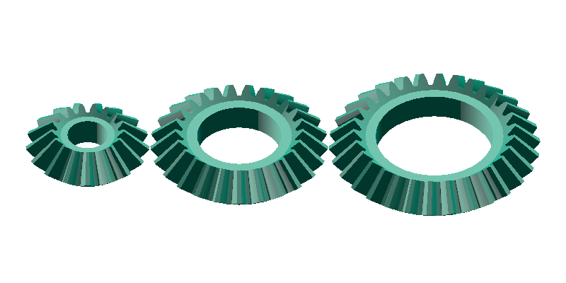
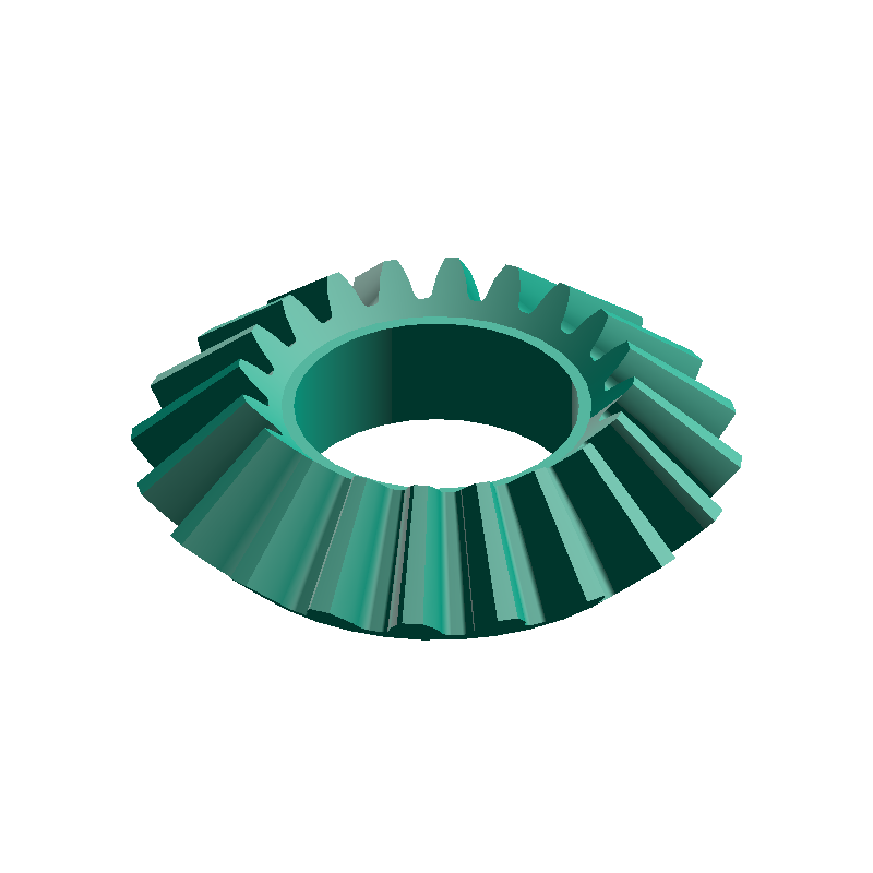
Put the other way around, matching the module is a prerequisite for meshing gears. Rack and pinion (spur gear + linear rack), bevel gear pairs, worm gear and worm wheel — every supported combination must be designed with the same module. Note that combinations with different shaft orientations (e.g., a spur gear with a bevel, or a spur gear with a worm wheel) will not mesh as-is even if their modules match.
Strictly speaking, the pressure angle (the tooth-form angle, typically 20°) must also match, but for DIY / 3D printing the common 20° tooth form is effectively the standard, and the meta-matic generators adopt it. Only when pairing with off-the-shelf gears, double-check the pressure angle marking just in case.
Module vs. tooth count
Module and tooth count are often confused, but they play different roles. The module sets "how big a single tooth is", while the tooth count sets "how many divisions you cut around the circumference". The two can be chosen independently, but both affect overall gear size through the pitch circle diameter d = m × z.
- Changing the module → changes the size of a single tooth (affects strength and mesh precision)
- Changing the tooth count → changes how the circumference is divided (affects reduction ratio and rotational resolution)
- Both affect the overall gear size through the pitch circle diameter
d = m × z
For example, if you want a "40 mm diameter pinion gear", choosing m = 1 × z = 40, m = 2 × z = 20, or m = 4 × z = 10 results in very different tooth sizes. The tooth count mainly affects the reduction ratio and rotational resolution, while the rotational speed itself is determined by the tooth-count ratio against the mating gear. A low-tooth-count pinion makes it easy to build a compact mechanism, and pairing it with a high-tooth-count gear yields a large reduction ratio.
Choosing a module by use case
Pick a module along three axes: physical size, strength, and 3D-printability. For industrial use, JIS defines a standard module series (0.5 / 0.8 / 1.0 / 1.25 / 1.5 / 2.0 / 2.5 / 3.0 / 4.0 / 5.0 ...), but for DIY and 3D printing you do not have to stick to the standard series — except when pairing with off-the-shelf gears.
| Module | DIY feel | 3D-printability | Typical uses |
|---|---|---|---|
| 0.5 | Precision instruments / small models | Tooth tips crumble — not recommended | Watch mechanisms, precision robotics, OK with SLA |
| 1.0 | Small mechanisms | Borderline usable | Desktop robots, small gearboxes |
| 1.5 – 2.0 | DIY sweet spot | Easiest to print | General DIY, CNC, 3D printer parts, educational kits |
| 3.0 | High-torque applications | Plenty of margin to print | Reducers, high-torque mechanisms, wooden toys |
| 5.0 and above | Heavy-machinery territory | Over-spec for printing | Industrial machinery, construction equipment, large jigs |
π × m / 2 ≒ 1.5708 × m, which works out to about 0.78 mm at m = 0.5. The actual tooth tip is even thinner because of the involute profile, so an FDM printer with a 0.4 mm nozzle cannot even lay down two extrusion widths across it. There is no room for infill, and the diagonal layering breaks the tooth tips into a crumbly mess. For FDM 3D printers, m = 1.5 or larger is strongly recommended (SLA or DLP can handle m = 0.5 in practice).When pairing with off-the-shelf gears, always match the module of the existing product. A common cause of mesh failure is combining a custom-made gear with an off-the-shelf pinion at a different module.
Generating on meta-matic
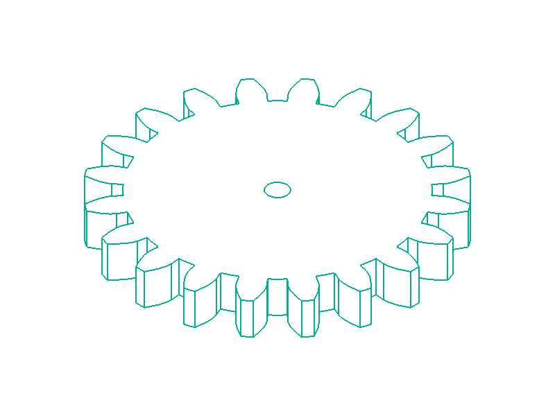
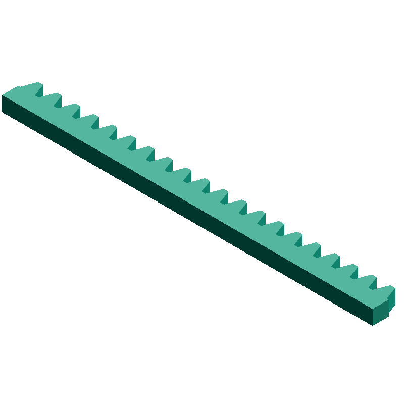
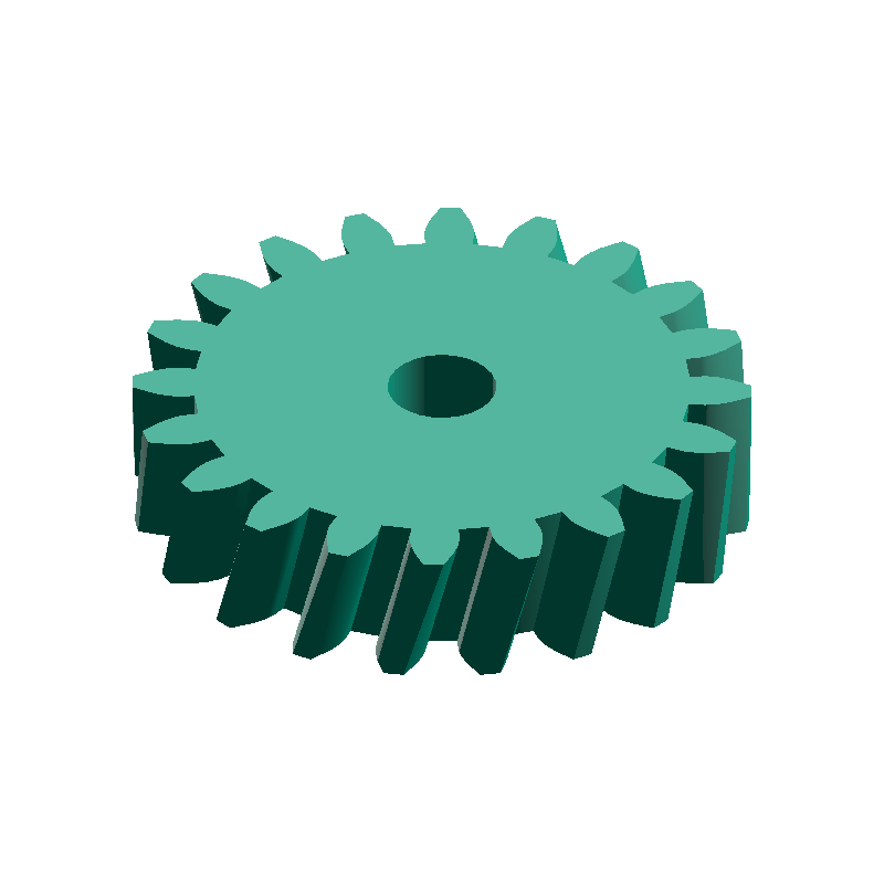
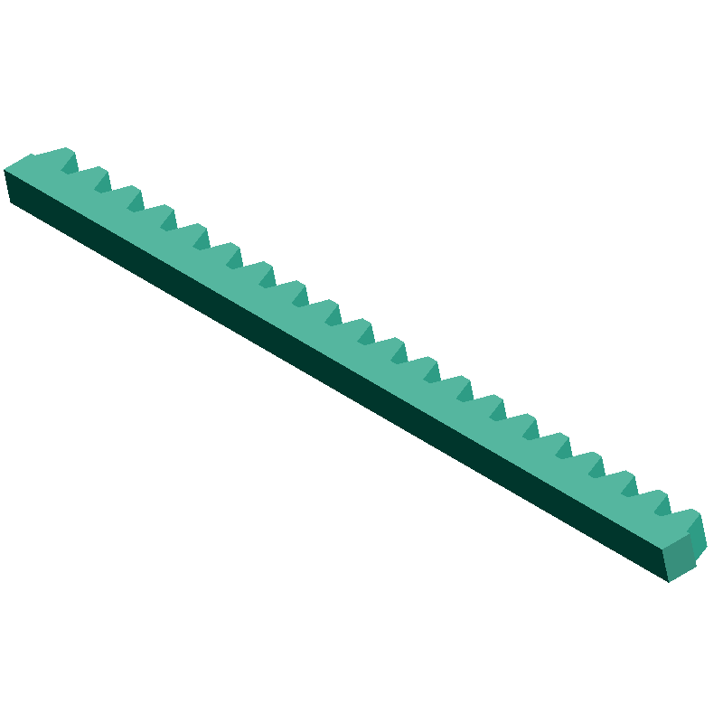
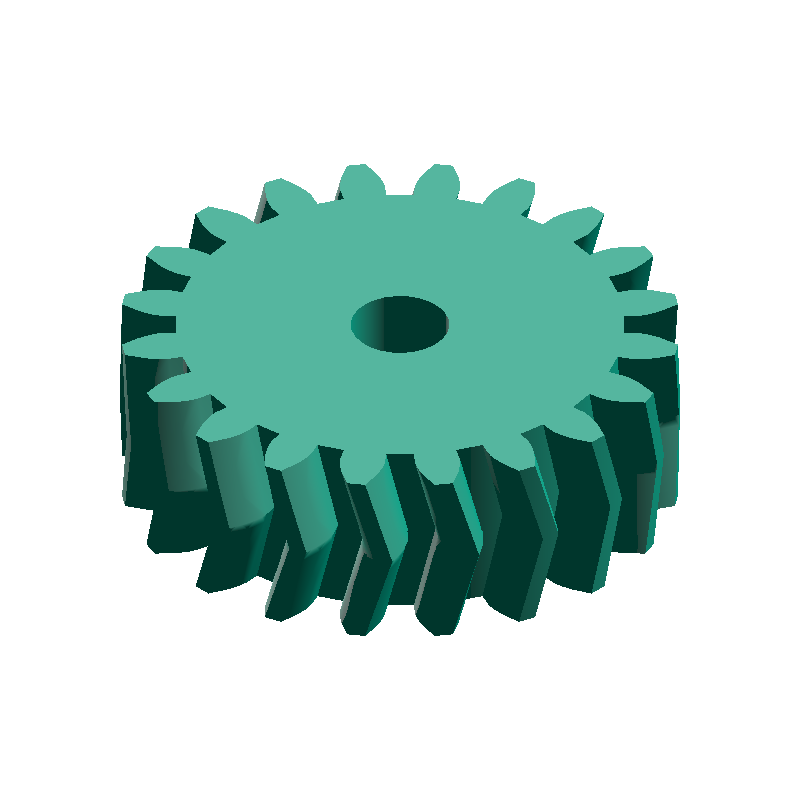
Once you have settled on a module, you can generate the 3D model of the corresponding gear on meta-matic. The key is to keep every gear in a meshing set at the same module. For example, when designing a rack-and-pinion mechanism, the spur gear and the rack must be generated at the same module value.
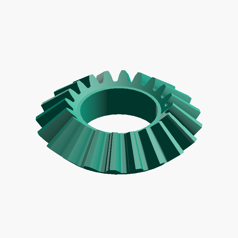
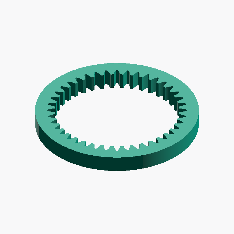
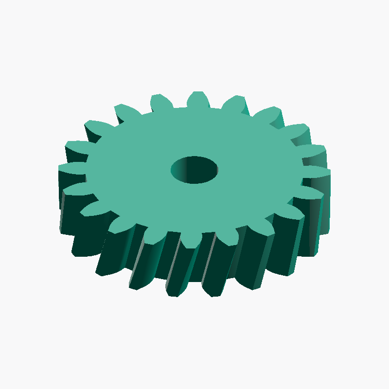
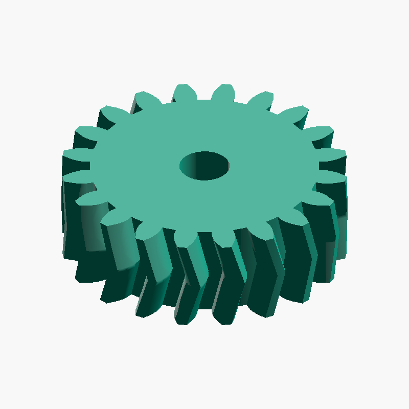
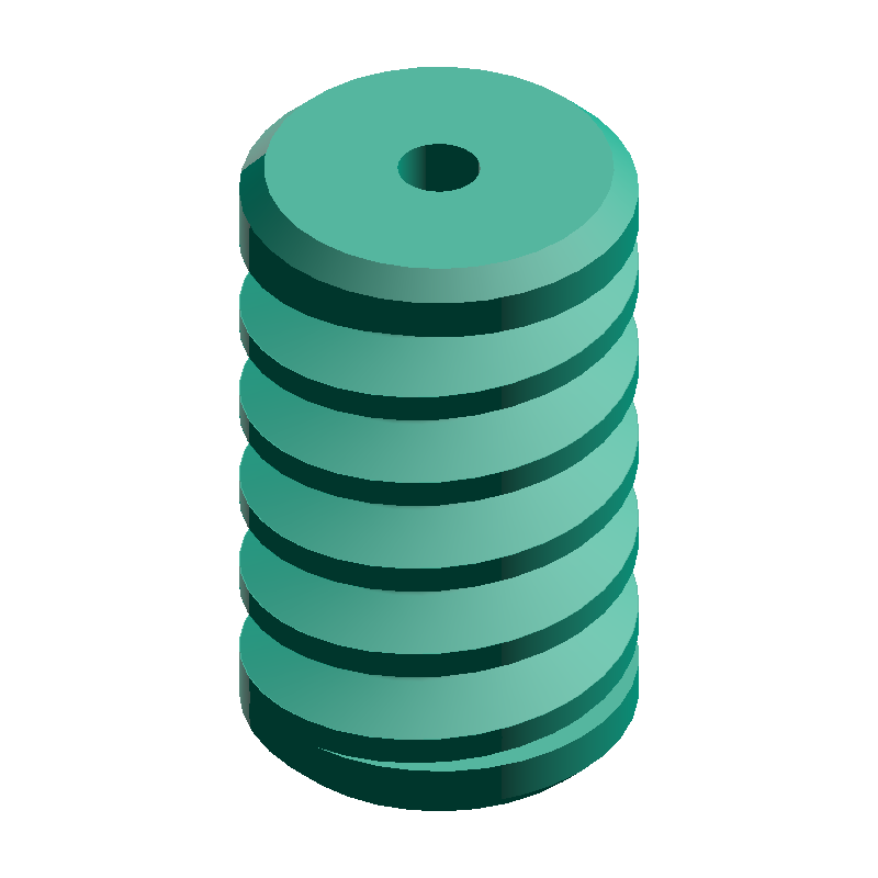
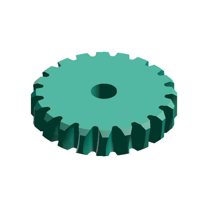
On general 3D-model sharing sites you can find generic spur gears, but matching a bevel gear or a worm wheel to an arbitrary module and tooth count is hard — usually you have to design it from scratch in CAD. meta-matic lets you generate spur, rack, bevel, worm, and helical gearing at the same module, so meshing pairs or sets come together with no manual effort.
Frequently asked questions
QWhat happens if I combine gears with different modules?
QWhat is the difference between module and DP (Diametral Pitch)?
m = 25.4 / DP. For example, DP = 24 corresponds to m ≈ 1.058. American gear catalogs are dominated by DP notation, so take care when mixing them with metric gears.QAre smaller modules higher performance?
QWhat is the best module for a 3D-printed gear?
m = 1.5 – 2.0 is the easiest to print. Anything m = 1 or below leaves the tooth tips so thin that layer-collapse risk goes up. SLA or DLP can handle m = 0.5 in practice, but for PLA or PETG filament it is safest to start around m = 2.