La cremallera y piñón es un mecanismo de engranaje básico que convierte el movimiento de rotación en movimiento lineal. Esta guía explica el funcionamiento del piñón (engranaje pequeño) y la cremallera, el cálculo del recorrido por vuelta (π×m×z), por qué ambos deben tener el mismo módulo, la elección del número de dientes del piñón y la longitud de la cremallera, la generación de archivos STEP con los generadores de engranaje recto y de cremallera, y los aspectos a tener en cuenta en la impresión 3D.
Cremallera y piñón: de la rotación al movimiento lineal
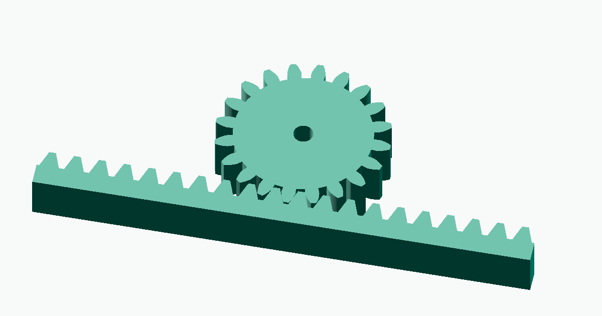
A rack and pinion is the most basic gear mechanism for converting rotary motion into linear motion. By meshing a rotating small gear (the pinion) with a flat, bar-shaped gear (the rack), the pinion's rotation becomes straight-line travel of the rack. It is used wherever rotation needs to become linear motion — feed drives on CNC machine tools, automotive steering, lift stages, and the axis drives of 3D printers. With meta-matic you generate the pinion with the Spur Gear generator and the rack with the Rack Gear generator, and simply combine the two to design this mechanism. This guide covers the principle of the rack and pinion, how to calculate travel, how to design the pinion and rack, and how to generate STEP files.
What is a rack and pinion?
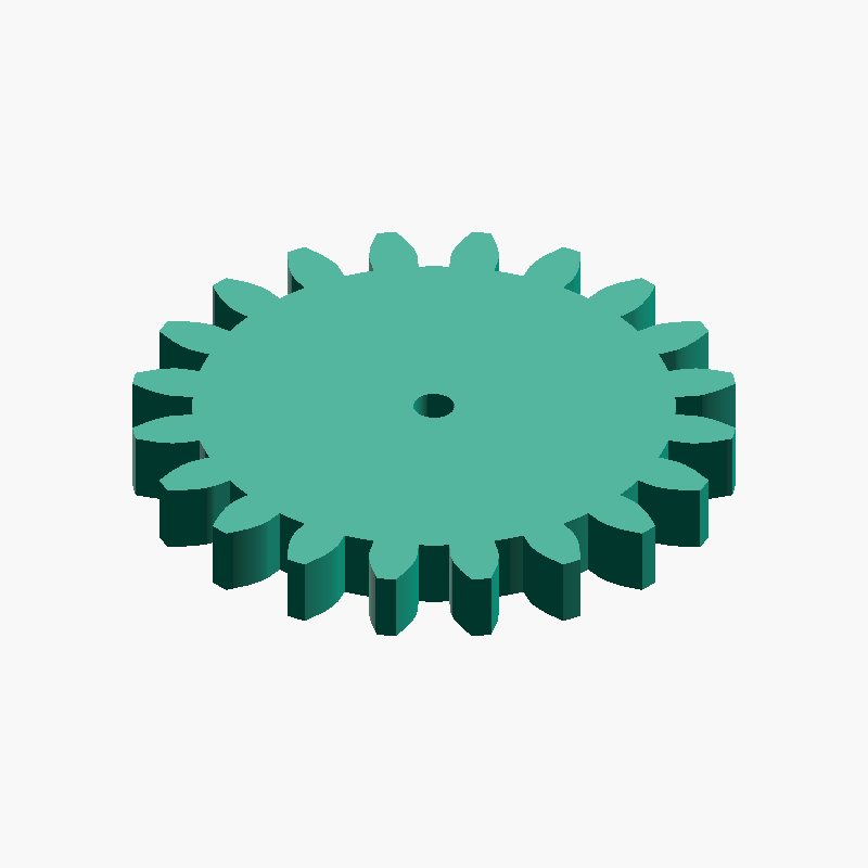
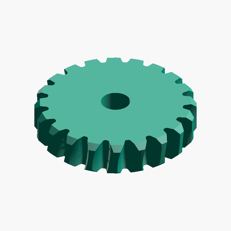
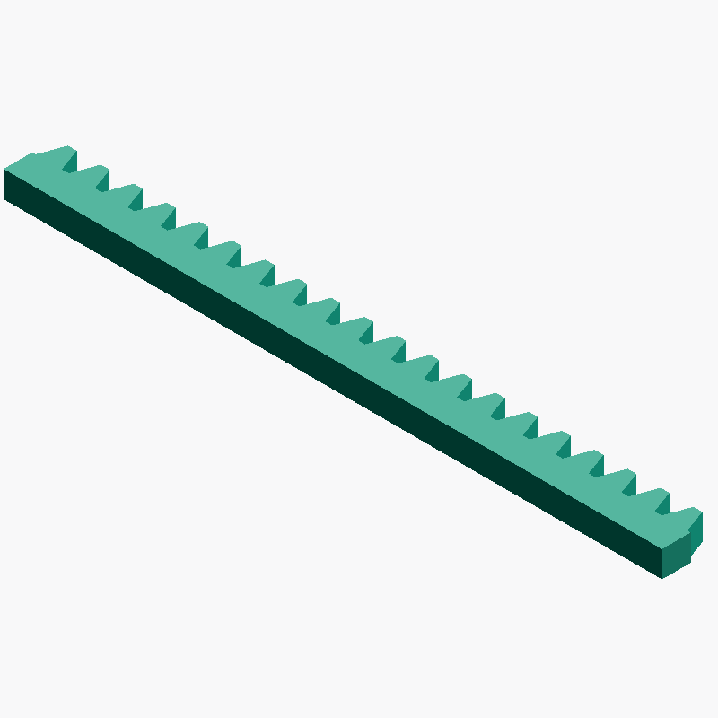
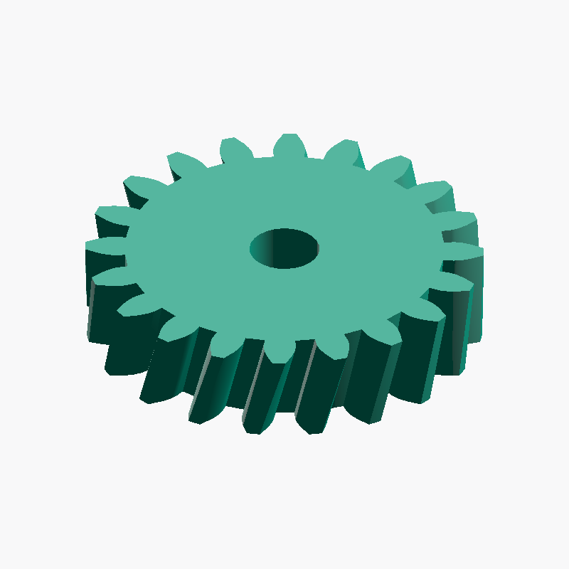
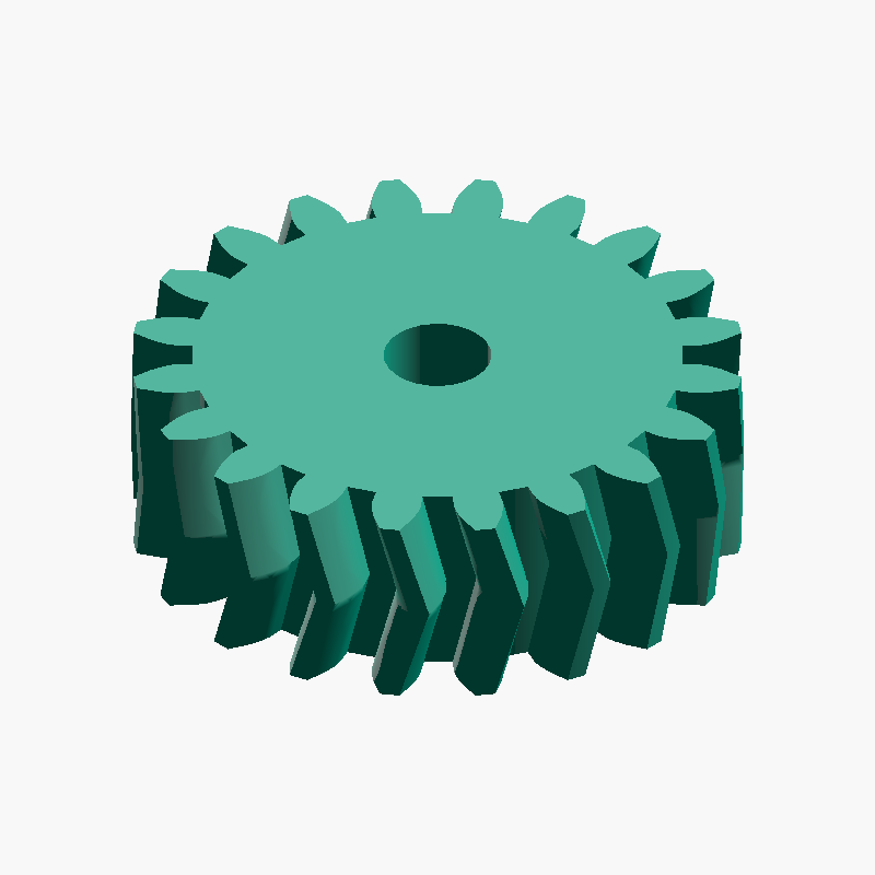
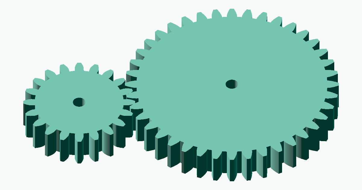
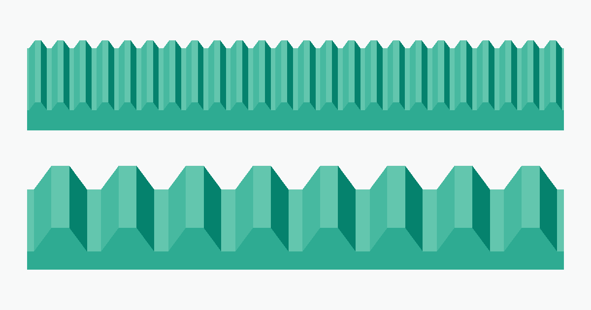
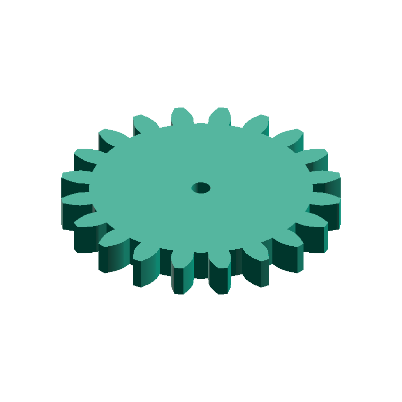
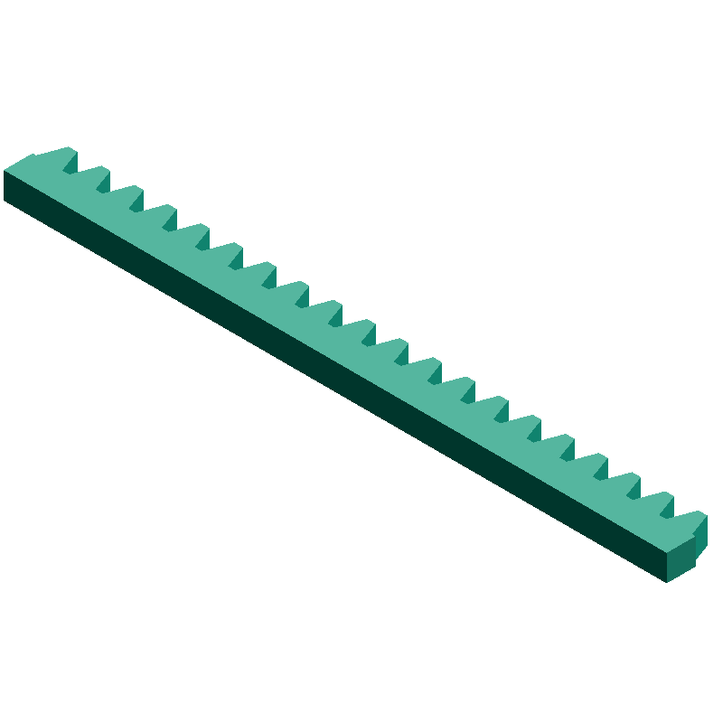
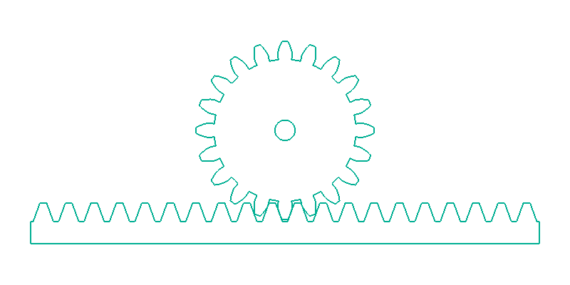
A rack and pinion is made up of two parts: the pinion (a small spur gear) and the rack (a straight, linear gear). The rack can be thought of as a spur gear whose pitch circle (reference circle) radius has been made infinite. As the radius approaches infinity the involute curve approaches a straight line, so the rack's tooth faces become straight (a trapezoidal tooth profile), and these straight faces mesh correctly with the pinion's involute teeth. As the pinion rotates, the engaged teeth push the rack and the rack moves in a straight line. Conversely, moving the rack rotates the pinion, so the conversion works both ways between rotation and linear travel.
meta-matic's pinion (spur gear) and rack share the same fixed parameters — a 20° pressure angle, addendum 1.0m, dedendum 1.25m, and 0 backlash. Generated with the same module, they produce tooth profiles that mesh correctly by design.
Advantages and disadvantages
Compared with other linear-motion mechanisms such as ball screws and belt drives, rack-and-pinion systems offer several advantages as well as some trade-offs to weigh when selecting a mechanism.
Main advantages
- Handles long strokes: making the rack longer (or splicing sections together) accommodates a large travel distance
- Well suited to high-speed motion: one pinion revolution moves
π×m×z, a large distance, so it suits fast feeds - Simple structure: the mechanism consists of only two primary components — a pinion and a rack — making it simple to design, manufacture, and prototype
Main disadvantages
- Prone to backlash: the gap between teeth produces a small amount of play (looseness)
- Lower positioning accuracy than a ball screw: for applications needing high positioning accuracy, a ball screw is usually the better choice
- Requires lubrication and wear management: grease metal-on-metal pairs, and consider wear and tooth chipping for plastics
Relationship between rotation and linear motion
The key feature of a rack and pinion is that the pinion's rotation and the rack's travel are proportional. For one full turn of the pinion, the rack moves a distance equal to the circumference of the pinion's pitch circle. Writing the pitch circle diameter as d, the module as m, and the pinion tooth count as z, since d = m × z, the travel per pinion revolution is given by the following formula.
Travel per pinion revolution = π × d = π × m × z
For example, a module-2, 20-tooth pinion moves π × 2 × 20 ≈ 125.7 mm per revolution. The travel when the pinion turns by θ degrees is (θ ÷ 360) × π × m × z. Thanks to this proportional relationship, combining it with a stepper motor lets you precisely control travel distance from the rotation angle.
| Pinion rotation | Travel formula | Example (m=2, z=20) |
|---|---|---|
| One revolution (360°) | π × m × z | 125.7 mm |
| Half revolution (180°) | π × m × z ÷ 2 | 62.8 mm |
| One tooth (360/z°) | π × m | 6.28 mm |
p = π × m. When the pinion turns by one tooth, the rack advances by one tooth pitch (π×m) as well. As long as the pinion and rack share the same module, this pitch matches and they mesh correctly.Designing the pinion and rack
When designing a rack and pinion, the fundamental premise is that the pinion and rack must use exactly the same module. If the modules differ, the tooth pitches do not match and they will not mesh at all. Once the module is matched, select the pinion's tooth count and the rack's length to suit your application.
- Module: set to the same value for pinion and rack. Larger means stronger teeth suited to high torque; smaller means finer and smoother
- Pinion tooth count: governs the travel per revolution (
π×m×z) and the outer diameter. The minimum is 17 teeth (the undercut limit) - Rack length: set it to the required travel (stroke) plus extra margin so the pinion still meshes at the ends
F = T ÷ r (T: motor torque, r: pitch circle radius), so for the same motor torque a larger pitch circle radius gives less thrust. In other words, compared at the same motor torque, fewer teeth (a smaller pitch circle radius) means slower motion but greater thrust. Choose the tooth count by balancing speed against force.Calculating key dimensions and travel
The key dimensions of a rack and pinion can be calculated from the module m and the pinion tooth count z. The dimensions you need for positioning during assembly are as follows.
| Name | Symbol / formula | Example (m=2, z=20) |
|---|---|---|
| Pinion pitch circle diameter | d = m × z | 40.00 mm |
| Pinion tip circle diameter | Da = m × (z + 2) | 44.00 mm |
| Travel per pinion revolution | π × m × z | 125.7 mm |
| Rack pitch | p = π × m | 6.28 mm |
The most important thing in assembly is the distance between the pinion's axis center and the rack's pitch line. Position the pinion axis at a distance of pitch radius = m × z ÷ 2 (for example, 20 mm at m=2, z=20) so that the pinion's pitch circle is exactly tangent to the rack's pitch line (the line lying one addendum m below the tooth tips). If this distance is too small the teeth bind, and if too large the play grows and the mechanism will not work correctly.
Example: driving with a stepper motor
Because the rack and pinion's rotation angle and travel are proportional, combining it with a stepper motor lets you control travel precisely in steps. It is a common configuration in DIY CNC, gantry, and XY-stage builds. The travel per step (the resolution) is given by the following formula.
Travel per step = π × m × z ÷ (steps per revolution)
For example, fitting a module-1, 20-tooth pinion to a typical NEMA17 stepper motor (200 steps per revolution) gives a resolution of π × 1 × 20 ÷ 200 ≈ 0.314 mm/step. Using 1/16 microstepping refines this further to 0.314 ÷ 16 ≈ 0.02 mm. To work out the resolution from the motor's step count and the pinion dimensions, the steps/mm calculator is handy.
How to generate STEP files
With meta-matic you generate the pinion and the rack with their respective generators and combine them in CAD. For both, you simply enter parameters in your browser to download a STEP file.
Decide the module
Decide a common module for the pinion and rack. Choose it from the required thrust, accuracy, and compatibility with mating parts.Generate the pinion
In the Spur Gear generator, enter the chosen module, pinion tooth count, bore diameter, and face width to generate the STEP file.Generate the rack
In the Rack Gear generator, enter the same module, the required tooth count (length), height, and width to generate the STEP file.Assemble in CAD
Open both files in Fusion 360 / SolidWorks / FreeCAD and position them so the distance from the pinion axis to the rack's pitch line equals thepitch radius(m×z÷2).Check the meshing
Rotate the pinion and verify in the assembly that the rack moves smoothly in a straight line, with no binding teeth or excessive play.
Notes on 3D printing and assembly
A rack and pinion can be made by 3D printing, but the smoothness of the linear motion depends on the tooth-face accuracy and the straightness of the rack. Keep the following points in mind to build a practical mechanism.
- Backlash (play): because this tool generates with zero backlash, the teeth can bind given typical 3D-printing tolerances. Slightly adjusting the center distance between the pinion and rack, or lightly finishing the tooth faces, can make the motion smoother
- Preventing rack warp: long racks tend to warp during printing. Improve bed adhesion and, if needed, print the rack in sections and join them
- Supporting the pinion shaft: if the pinion floats, the mesh becomes shallow. Support it firmly with bearings and keep its distance from the rack constant
- Print orientation: printing the rack with its tooth faces upward and the pinion with its axis along the Z-axis tends to give better tooth-profile accuracy
- Material: PLA or PETG for general use; Nylon and similar where wear is a concern
Frequently asked questions
QDo the pinion and rack need to have the same module?
QHow long should the rack be?
QWhat is a rack and pinion used for?
QIs there a minimum number of teeth for the pinion?
QWhat positioning accuracy can I achieve?
Related resources
Here are generators useful for rack-and-pinion design, along with related guides and calculation tools. Use them as needed.
- Spur gear guide — how to choose the tooth count, bore, and face width of the spur gear used as the pinion
- Gear module guide — how to decide the module and combine with off-the-shelf gears
- steps/mm calculator — automatically calculates the travel per step from the step count and pinion dimensions
- Gear ratio calculator — automatically calculates the reduction ratio from the driving and driven tooth counts