Planetary Gear Tooth Count & Assembly Calculator
Enter the tooth counts of the sun and planet gears and the number of planets to calculate the ring gear tooth count and reduction ratio, and check whether the planetary gear set can be assembled (equal-spacing assembly, adjacency and interference). Placement coordinates and rotation angles for CAD assembly are also provided.
HOW-TO How to Calculate Planetary Gear Tooth Counts and Assembly Conditions +
- Enter the module, sun gear teeth, planet gear teeth and number of planets, and select the fixed member.
- The ring gear tooth count, reduction ratio, key dimensions and the assembly, adjacency and interference checks are displayed in real time.
- If the set is feasible, create the parts from the links to each gear's 3D generator page, then assemble them using the CAD assembly angle table.
Result
- Overall Result
- —
- Coaxial Condition
- —
- Equal-Spacing Assembly Condition
- —
- Adjacent Planet Clearance
- —
- Involute Interference
- —
The adjacent planet clearance is below the warning threshold. The set can be assembled, but there may not be enough margin for printing errors in 3D printing.
Not feasible, so the 3D generator links and CAD assembly angles are not shown.
- Ring Gear Teeth (Zr)
- — teeth
- Center Distance (a)
- — mm
- Carrier Pin Circle Diameter (Dc)
- — mm
- Pitch Circle Diameter (Sun)
- — mm
- Pitch Circle Diameter (Planet)
- — mm
- Pitch Circle Diameter (Ring)
- — mm
- Tip Circle Diameter (Sun)
- — mm
- Tip Circle Diameter (Planet)
- — mm
- Tip Circle Diameter (Ring, inner)
- — mm
- Root Circle Diameter (Sun)
- — mm
- Root Circle Diameter (Planet)
- — mm
- Root Circle Diameter (Ring, outer)
- — mm
- Recommended Ring Gear Outer Diameter (De)
- — mm
- Output Speed
- — RPM
- Planet Spin Relative to Carrier
- — RPM
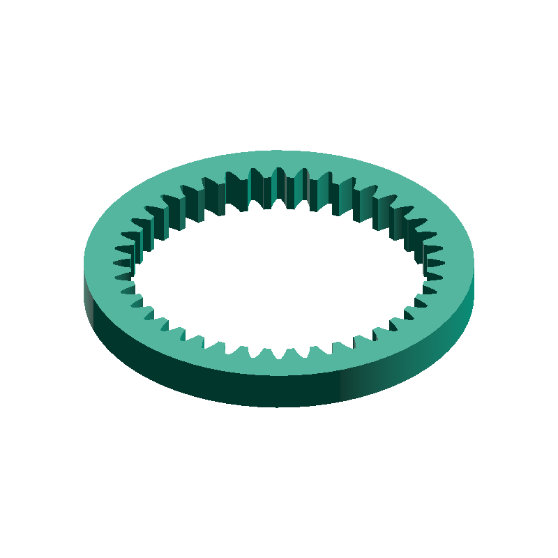
Generate 3D Models with These Conditions

CAD Assembly Angles
The origin is the center of the sun gear and the gear axis is the Z axis; angles are positive counterclockwise when viewed from the +Z side. Each gear's orientation as output by the 3D generator is 0°. Rotate each planet by θ about its own center first, then move it to its center coordinates.
| Planet | Placement Angle φ (°) | X (mm) | Y (mm) | Rotation θ (°) |
|---|
- Ring Gear Rotation θr
- —°
17–86 teeth
17–51 teeth (ring gear teeth Zs + 2×Zp must be 120 or less)
2–12 (equally spaced)
The input, output and reduction ratio depend on which member is fixed
Rotational speed of the input member. Leave blank to hide speeds
Checks geometric assemblability assuming a standard 20° involute profile, no profile shift and equally spaced planets. Strength, service life, efficiency and manufacturing tolerances are not covered. In 3D printing, meshing may be poor due to printing errors or shrinkage even when the set is feasible.
- ⚙️ Gear Ratio Calculator Calculate gear ratio, output speed, and torque from driver and driven tooth counts (multi-stage)
- ↔️ Spur Gear Center Distance Calculator Calculate spur gear center distance and key dimensions from the module and two gear tooth counts
- ➰ V-Belt Length & Center Distance Calculator Calculate the recommended belt designation, actual center distance, wrap angle and belt speed from the belt type and effective pulley diameters