Uma engrenagem cilíndrica transmite potência entre dois eixos paralelos e é o tipo de engrenagem mais básico. Este guia explica como escolher o módulo, o número de dentes, o furo e a largura, as fórmulas das dimensões principais (diâmetros primitivo, externo e de raiz), por que engrenagens que engrenam precisam ter o mesmo módulo e dicas de impressão 3D, incluindo por que menos de 17 dentes não é possível (interferência).
Guia de engrenagem cilíndrica: módulo, dentes, furo e largura
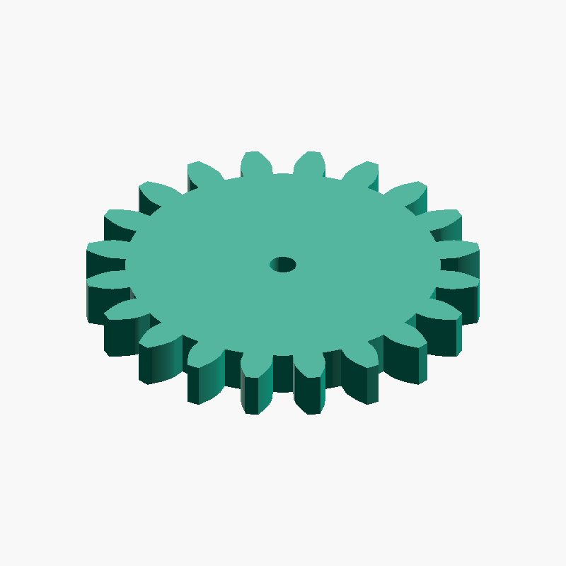
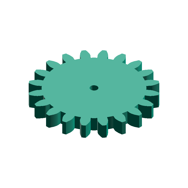
A spur gear is the most basic type of gear, transmitting rotation and power between two parallel shafts. With teeth cut straight and parallel to the axis, it is simple to design and manufacture, and is used in applications ranging from robots and DIY projects to 3D-printed mechanisms. With meta-matic's spur gear generator you only specify four values — module / number of teeth / bore diameter / face width — to produce a 3D model. This guide covers the basic structure of spur gears, how to choose the module, teeth, bore, and face width, how to calculate key dimensions such as the pitch circle diameter, and tips for 3D printing.
What is a spur gear?
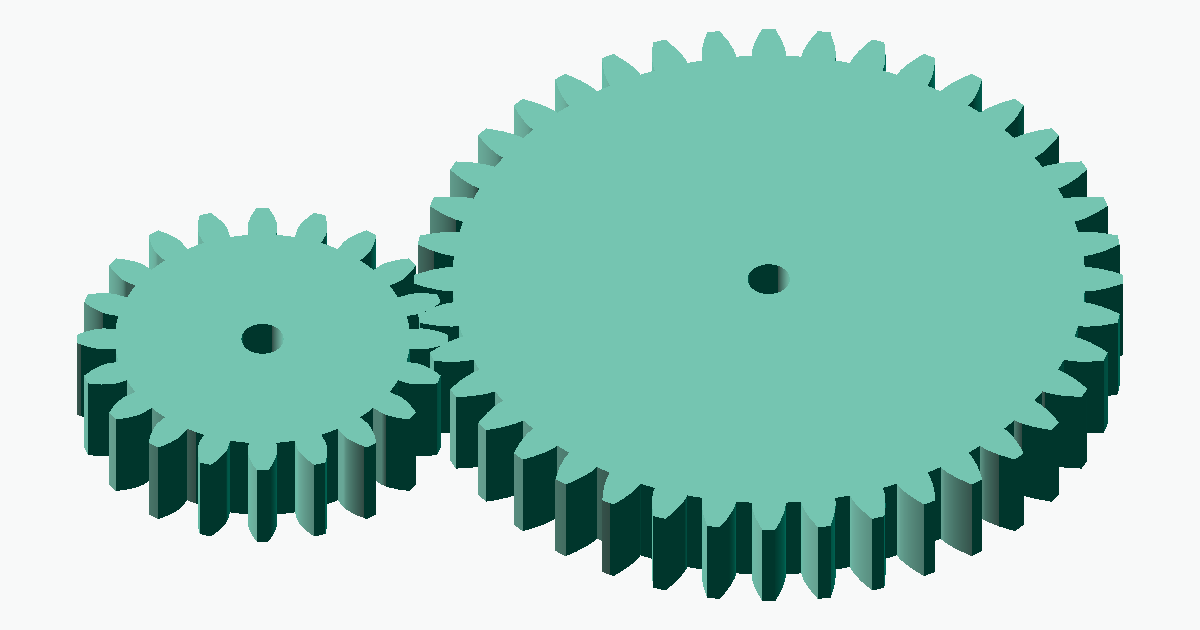
A spur gear uses a smooth curve called the involute for its tooth profile. The involute profile keeps the speed ratio constant as two meshing gears rotate and tolerates small errors in center distance, which is why it has become the mainstream for mechanical gears. Two meshing spur gears rotate in opposite directions.
meta-matic's spur gear generator holds fixed parameters internally — 20° pressure angle, addendum 1.0m, dedendum 1.25m, and 0 backlash — and produces shapes conforming to the JIS B 1701-1 / ISO 53 standard basic rack tooth profile.
How to choose the module
The module (symbol m) is the standard value that determines tooth size; it relates to the pitch circle diameter by d = m × z (module × number of teeth). A larger module means larger, stronger teeth, while a smaller module means finer, more compact teeth. The most important rule is that meshing gears must have the same module. As a rough guide: 0.5–1 for small devices, 1–2 for robots and DIY, and 3 or more for high-torque uses. How to decide the module and how to mesh with off-the-shelf gears are explained in detail in the related article.
How to choose the number of teeth
The number of teeth can be set in the range 17–120. It is the most fundamental parameter governing the gear's outer diameter and reduction ratio. For the same module, fewer teeth make the gear smaller and more compact, while more teeth make it larger and make it easier to achieve a large reduction ratio with the mating gear.
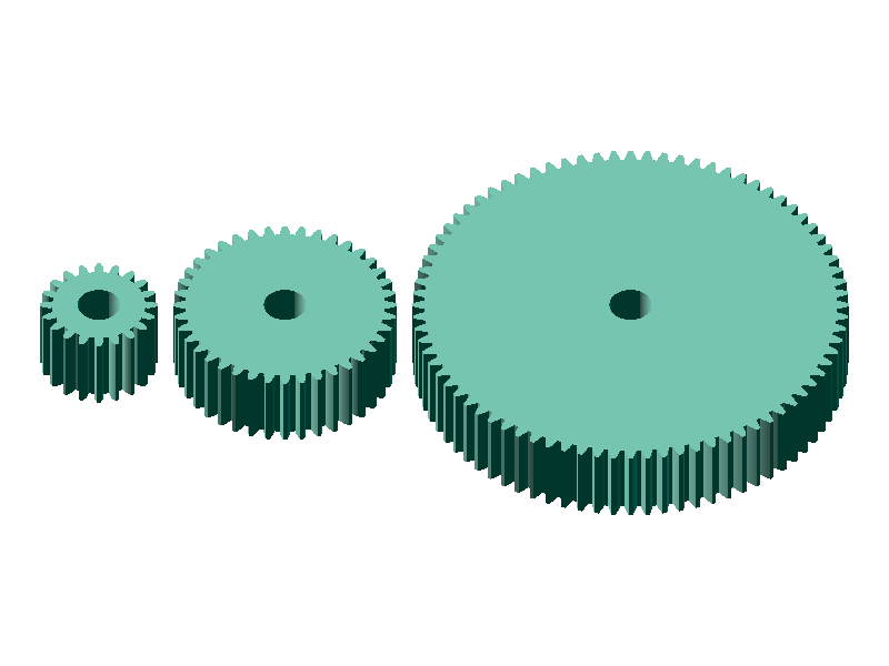
- Fewer teeth (17–20): small and compact; often used as a pinion (small gear) on the driving side
- More teeth (40+): larger diameter and easier to get a large reduction ratio; suited to the larger driven gear
- Gear ratio: for one gear pair it is determined by "driven teeth ÷ driving teeth"
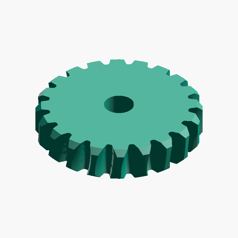
How to choose the bore diameter
The bore diameter is set from 0 to 100 mm; specifying 0 produces a spur gear with no bore. Basically match it to the shaft diameter. As a starting point, increasing the bore diameter by approximately 0.1–0.2 mm can compensate for typical FDM printing tolerances and make the shaft easier to insert after printing.
- Bore 3–5 mm: common for small motors and hobby shafts
- Bore 6–8 mm: medium mechanisms and metal shafts
- Bore = 0 (solid center): choose when you want to machine it later in CAD
0 and post-process in CAD software such as Fusion 360 or FreeCAD.How to choose the face width
The face width can be set in the range 1.0–50 mm. A wider face increases the tooth contact area and the transmittable torque, but it also adds weight and lengthens 3D-printing time. As a guide, a face width of about 6–10 times the module (e.g. 12–20 mm for m=2) balances strength and practicality well.
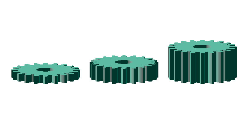
- Narrow face: light and fast to print, but low transmittable torque
- Wide face: higher strength and torque, but heavier and slower to print
Calculating key dimensions
The key dimensions of a spur gear can be calculated from just two values: the module m and the number of teeth z. meta-matic's generator screen also shows the pitch circle diameter and other values automatically as you enter inputs.
| Name | Symbol | Formula | Example (m=2, z=20) |
|---|---|---|---|
| Pitch circle diameter | d | m × z | 40.00 mm |
| Tip circle diameter | Da | m × (z + 2) | 44.00 mm |
| Root circle diameter | Df | m × (z − 2.5) | 35.00 mm |
| Circular pitch | p | π × m | 6.28 mm |
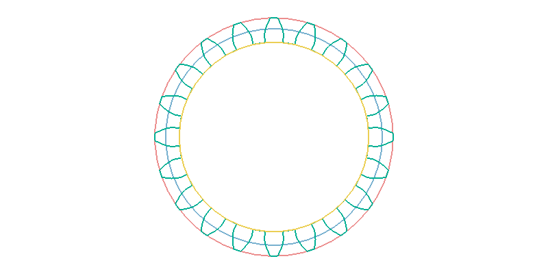
- Tip circle (Da): the circle through the tooth tips; corresponds to the outer diameter
- Pitch circle (d): the reference circle for meshing; the central dimension in gear design
- Root circle (Df): the circle through the tooth roots (bottoms)
The center distance between two meshing spur gears is given by a = m × (z1 + z2) ÷ 2. For example, meshing a 20-tooth and a 40-tooth gear at m=2 gives a center distance of 2 × (20 + 40) ÷ 2 = 60 mm. With meta-matic's spur gear center distance calculator, you can automatically compute the center distance, pitch circle diameter, tip circle diameter, and root circle diameter all at once just by entering the module and the two tooth counts.
How to generate a STEP file
meta-matic's spur gear generator lets you download a STEP file instantly just by entering parameters in your browser.
Decide the module
Choose the same module as the gear it will mesh with. If used on its own, decide the module from the required strength and size.Decide the number of teeth
Decide from the required reduction ratio and outer diameter. You can check the gear ratio of the driving and driven sides with the gear ratio calculator.Decide the bore and face width
Enter the bore to match the shaft diameter and the face width to match the required torque. For 3D printing, make the bore slightly larger.Generate and download in the generator
Enter the values above and press "Download STEP File" to download the STEP file automatically. If you want to check the shape first, press "Preview STEP Model" to inspect the 3D model and then download it manually.Open and check in CAD
Open it in Fusion 360 / SolidWorks / FreeCAD and verify the center distance and meshing with the mating gear in an assembly.
Notes on 3D printing
Spur gears have a relatively simple tooth profile and are well suited to 3D printing, but tooth-face accuracy governs how smoothly they mesh. Keep the following points in mind to print practical gears.
- Material: PLA or PETG for general use; Nylon and similar for high-load uses
- Print orientation: printing with the gear axis aligned with the Z-axis makes the tooth profile perpendicular to the layers, improving accuracy
- Shrinkage: specify the bore
+0.1 to 0.2 mmlarger and finish with a reamer if needed - Layer height:
0.16 mm or lessmakes the tooth faces smoother and reduces meshing noise
Frequently asked questions
QDo gears with different modules mesh?
QDo gears mesh even with different numbers of teeth?
QCan I make a spur gear with fewer than 17 teeth?
QAre 3D-printed spur gears practical?
QCan I edit the generated STEP file in Fusion 360 or FreeCAD?
Related resources
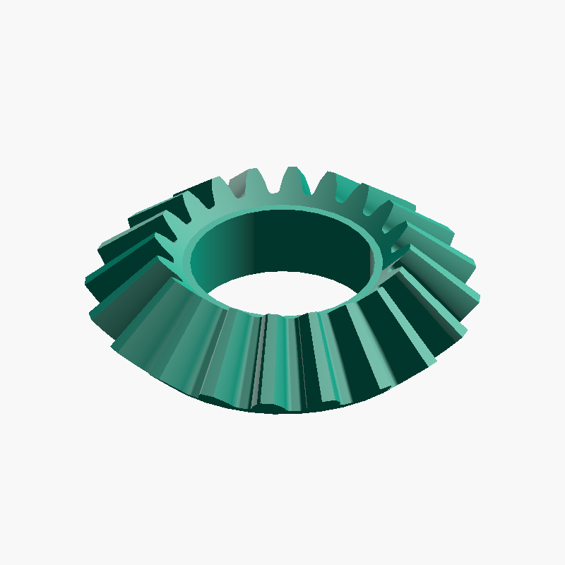
Here are gears often combined with spur gears and calculation tools useful for design. Use them as needed.
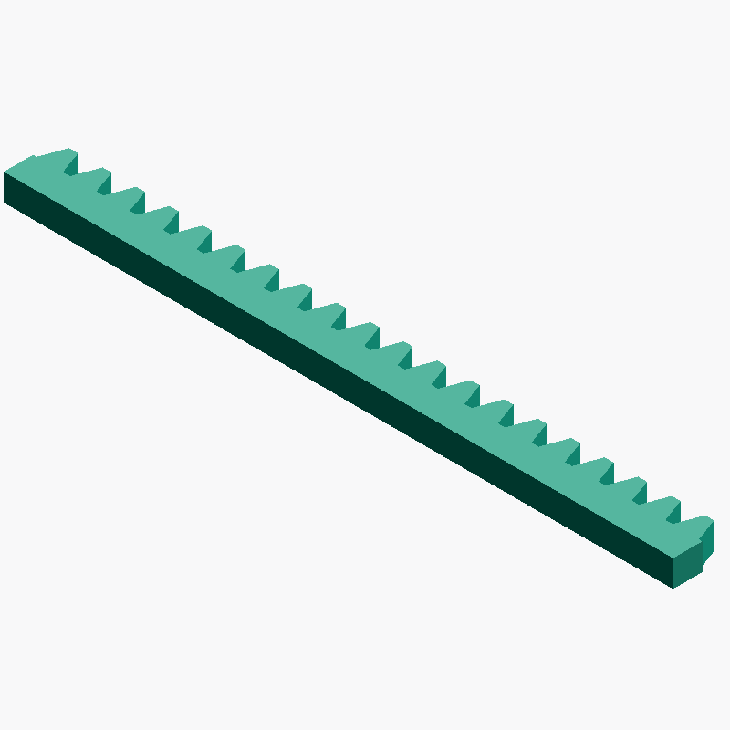
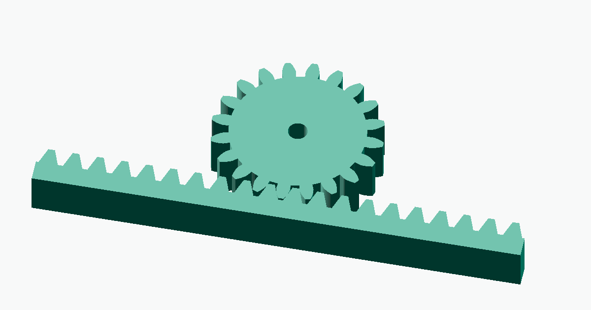
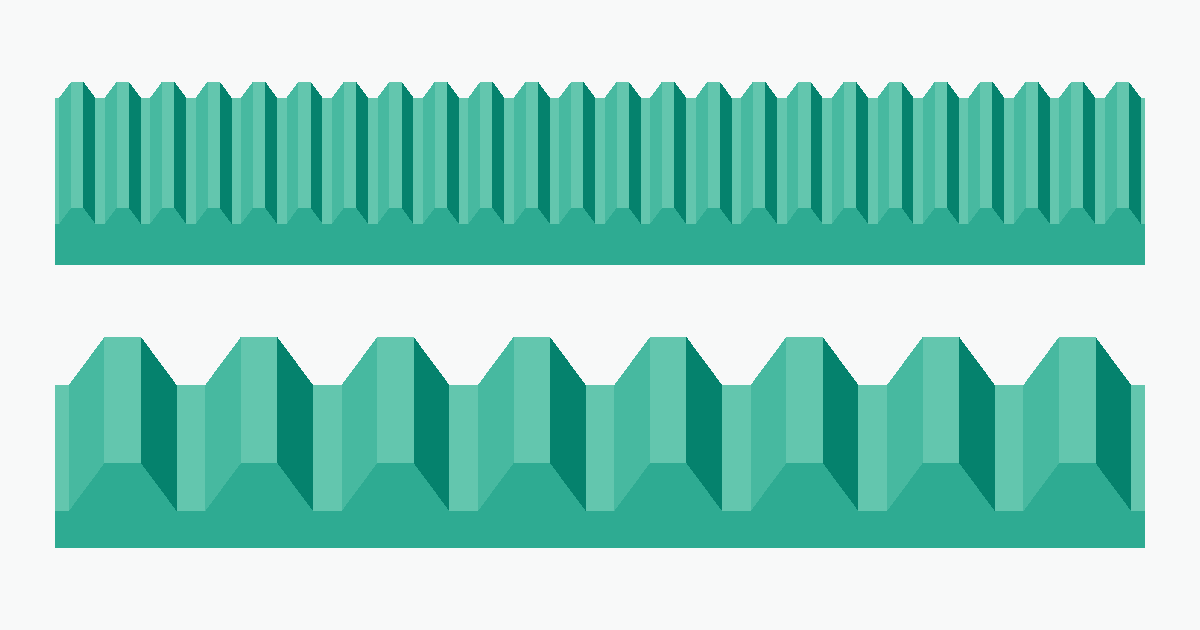
- Rack gear generator — for building rack-and-pinion mechanisms
- Gear ratio calculator — automatically calculates the reduction ratio from the driving and driven tooth counts
- Spur gear center distance calculator — automatically calculates the center distance and key dimensions from the module and the two tooth counts