Un rotismo epicicloidale è composto da solare, satelliti, corona e portasatelliti e offre un grande rapporto di riduzione con ingresso e uscita sullo stesso asse. Questa guida spiega come il membro fisso determina il rapporto, come la condizione di coassialità e l'interferenza con la corona limitano il numero di denti, come le condizioni di montaggio e di adiacenza limitano il numero di satelliti, come generare i file STEP e posizionarli in CAD e a cosa prestare attenzione nella stampa 3D.

Rotismo epicicloidale: rapporto, montaggio, satelliti
A planetary gear set is a gear mechanism in which several planet gears revolve around a central sun gear, surrounded by an internal (ring) gear. It delivers a large reduction ratio while keeping the input and output shafts on the same axis, and because the load is shared among several gears, it makes compact yet strong reducers possible. With meta-matic you generate the sun and planet gears with the Spur Gear generator, the ring gear with the Internal Gear generator, and choose the tooth counts and number of planets with the Planetary Gear calculator. This guide covers how the fixed member determines the reduction ratio, the conditions on tooth counts for assembly, how to choose the number of planets, and how to generate STEP files and assemble them in CAD.
What is a planetary gear set?
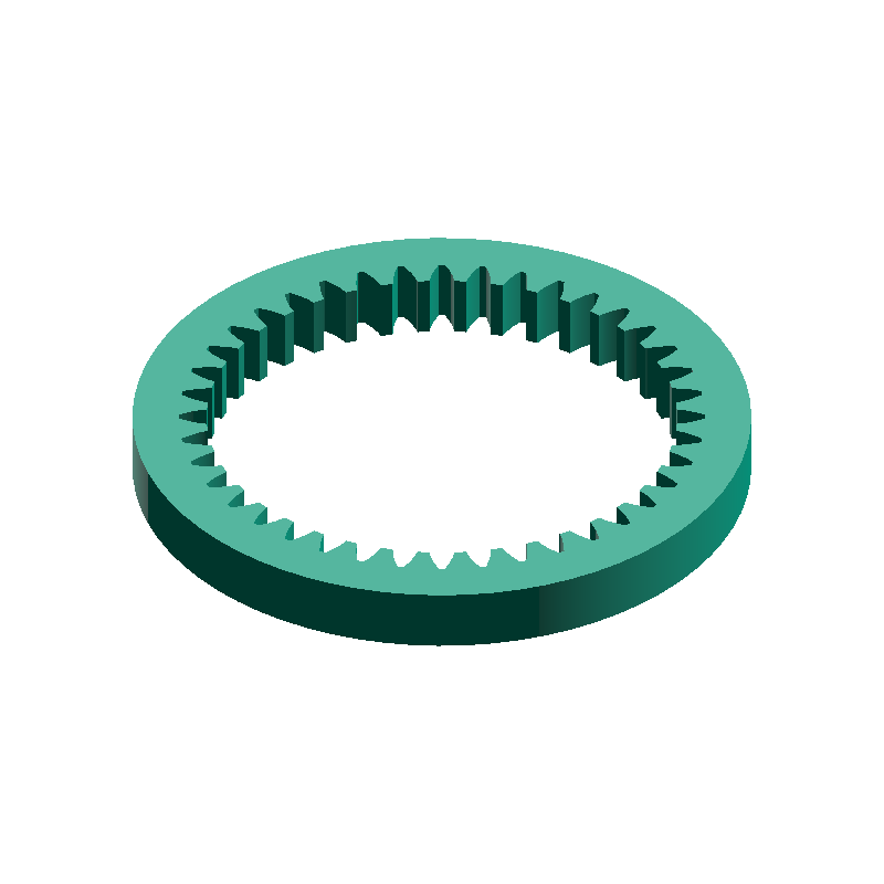
A planetary gear set consists of four members: the sun gear, the planet gears, the internal gear (ring gear), and the carrier that holds the planet shafts. Each planet meshes with both the sun gear and the ring gear; it turns about its own axis (rotation) while travelling around the sun gear together with the carrier (revolution). Because the sun gear, ring gear and carrier share one axis, the input and output line up on a single straight line.

Planetary gear sets are widely used where a large speed change is needed in a small space — automatic transmissions and the power-split devices of hybrid cars, internal-gear bicycle hubs, wind turbines, and gear units for all kinds of industrial machinery.
meta-matic's spur gears and internal gears are both generated with a 20° pressure angle, a standard addendum of 1.0m, a dedendum of 1.25m, no profile shift and 0 backlash. The conditions in this guide and the calculator's checks assume this tooth profile.

Fixed member and reduction ratio
In a planetary gear set, of the sun gear, ring gear and carrier, one is held fixed, one is the input and one is the output. Which member is fixed determines the reduction ratio and the direction of rotation. With the tooth counts of the sun gear Zs and the ring gear Zr, the three combinations are as follows.
| Fixed member | Input → output | Reduction ratio | Direction | Example (Zs=20, Zr=70) |
|---|---|---|---|---|
| Ring gear (Planetary type) | Sun gear → carrier | 1 + Zr/Zs | Same | 4.500 |
| Sun gear (Solar type) | Ring gear → carrier | 1 + Zs/Zr | Same | 1.286 |
| Carrier (Star type) | Sun gear → ring gear | −Zr/Zs | Reversed | −3.500 |
The largest reduction ratio comes from fixing the ring gear. If the carrier is fixed instead, the planets only turn about stationary shafts and act as idler gears that reverse the direction. The mechanism then behaves like an ordinary gear train.
Finding the reduction ratio in two steps
Because the planets revolve, the reduction ratio cannot be read directly from the tooth-count ratio. Instead, think of it in two steps. ① Hold the carrier and turn the sun gear one revolution. This is the same motion as an ordinary gear train. ② Keep the gears in mesh and turn the whole mechanism as a single block. Every member turns through the same angle and the meshing does not change. If step ② turns everything by exactly the amount that returns the ring gear moved in step ①, then the sum of ① and ② leaves the ring gear stationary — which is the motion with the ring gear fixed.
| Member | ① Carrier held, sun +1 | ② All turned +Zs/Zr | ①+② |
|---|---|---|---|
| Sun gear | +1 | +Zs/Zr | 1 + Zs/Zr |
| Planet gear | −Zs/Zp | +Zs/Zr | −Zs/Zp + Zs/Zr |
| Ring gear | −Zs/Zr | +Zs/Zr | 0 (fixed) |
| Carrier | 0 | +Zs/Zr | Zs/Zr |
Taking the ratio of the sun gear (input) speed to the carrier (output) speed gives (1 + Zs/Zr) ÷ (Zs/Zr) = 1 + Zr/Zs, the reduction ratio in Table 1. The idea rests on the principle that seen from the carrier, the relative rotations of the gears are in the same ratio as in an ordinary gear train. It was set out by Robert Willis in the 19th century, and the calculator uses the same relationship to compute rotational speeds.
Choosing the tooth counts
The calculator takes two tooth counts: the sun gear Zs and the planet gear Zp. The ring gear tooth count Zr follows automatically from these two. This section explains the two conditions the tooth counts must satisfy: the coaxial condition and interference with the ring gear.
Coaxial condition (the ring gear tooth count is determined automatically)
Each planet meshes with both the sun gear and the ring gear. The center distance between sun and planet must equal the center distance between planet and ring gear, so for standard gears (no profile shift) the ring gear tooth count is given by the following formula.
Zr = Zs + 2 × Zp
For example, Zs = 20 and Zp = 25 give Zr = 70. Substituting this into the reduction ratio with the ring gear fixed gives 1 + Zr/Zs = 2 + 2 × Zp/Zs, which shows that the larger the planets are relative to the sun gear, the larger the reduction ratio. It also shows that the reduction ratio is always greater than 2.
Zr = Zs + 2 × Zp while still matching the center distances. One 3D-printed planetary reducer, for instance, combined a 15-tooth sun, 22-tooth planets and a 60-tooth ring gear (15 + 2 × 22 = 59 ≠ 60) using profile shift. meta-matic's generators do not support profile shift, so the calculator also handles only tooth counts that satisfy the coaxial condition.Interference with the ring gear and the minimum planet tooth count
When an external gear meshes with an internal gear, types of interference occur that do not arise between two external gears. The three typical ones are listed below.
- Involute interference : the tips of the internal gear dig into the roots of the external gear (planet). It tends to occur when the external gear has few teeth
- Trochoid interference : the tips of the external gear hit the internal gear's teeth as they come out of mesh. It occurs when the difference between the two tooth counts is small
- Trimming interference : when the tooth counts are close, the external gear cannot be moved in or out radially. It can still be assembled by inserting it axially
In a planetary gear set the tooth-count difference between ring gear and planet, Zr − Zp = Zs + Zp, is large, so trochoid and trimming interference are not a problem in the normal range. What matters is involute interference, which sets a minimum planet tooth count for each ring gear tooth count.
| Ring gear teeth Zr | Minimum planet teeth |
|---|---|
| 51–52 | 22 |
| 53–63 | 21 |
| 64–85 | 20 |
| 86–120 | 19 |
As noted above, the large tooth-count difference means trimming interference does not normally occur. Even if a planet cannot go in radially, a spur gear with straight teeth can be assembled by sliding the planet into the ring gear axially. For tooth forms that cannot be inserted axially, such as double-helical gears, the ring gear is sometimes split in half and fitted from both sides.
Number of planets
The number of planets N is subject to two geometric conditions: whether the planets can be fitted at equal spacing (the equal-spacing assembly condition) and whether neighboring planets clear each other (the adjacency condition). On top of these, consider how many planets share the load well.
Equal-spacing assembly condition
For planets placed at equal spacing (every 360°/N) to engage both the sun gear and the ring gear, the following value must be an integer.
(Zs + Zr) ÷ N = integer
For example, with Zs = 20 and Zr = 70, (20 + 70) ÷ 3 = 30, so three planets fit. With four planets, 90 ÷ 4 = 22.5, so they do not. A common misconception is the condition that "the sun gear and ring gear tooth counts must each be divisible by N", but that rejects combinations that can actually be assembled. The check uses the sum of the tooth counts.
The condition can be derived by requiring that the path joining neighboring planets along arcs of the ring gear, planet and sun gear pitch circles be an integer multiple of the tooth pitch. The planets are equally spaced so that the radial forces on the bearings supporting the sun gear and the carrier cancel out. Unequal spacing relaxes the condition but upsets the rotational balance. meta-matic's calculator handles equal spacing only.
Interference between neighboring planets (adjacency condition)
Adding planets brings neighboring planets closer together. Unless the distance between planet centers is larger than the planet's tip diameter, the tips collide. meta-matic's calculator computes this margin (the adjacent planet clearance) with the following formula.
g = 2a × sin(180°/N) − m × (Zp + 2) (a = center distance = m × (Zs + Zp) ÷ 2)

If g is zero or less, neighboring planets collide and the set cannot be assembled. Zero is the boundary where the tips just touch, and in practice a margin is needed. The calculator shows "Feasible (caution)" when g is less than 0.5m; this threshold is this site's own setting, chosen to allow for 3D printing errors. The NASA paper imposes a margin of two addenda (2m) between neighboring planets as a design condition.
Adding planets lowers the maximum reduction ratio that the adjacency condition allows. Enumerating every tooth-count combination that the calculator judges feasible gives the following maximum reduction ratios with the ring gear fixed.
| Number of planets N | Maximum reduction ratio | Tooth counts Zs / Zp |
|---|---|---|
| 2 | 8.000 | 17 / 51 |
| 3 | 7.765 | 17 / 49 |
| 4 | 6.000 | 22 / 44 |
| 5 | 4.412 | 34 / 41 |
| 6 | 3.767 | 43 / 38 |
| 8 | 3.088 | 57 / 31 |
Including the "Feasible (caution)" combinations raises the limit to 6.182 for four planets and 4.545 for five. Conversely, requiring a margin of at least 2m lowers it to 5.667 for four planets and 4.286 for five. The same paper reports that its designs were limited to a maximum ratio of 4 with five planets and 5 with four planets, and the same trend appears in these results.
How many planets to use
Adding planets looks as if it should reduce the load on each one, but in practice manufacturing errors usually prevent the load from being shared evenly. With three planets, letting one of the sun gear, ring gear or carrier float radially so that it can move freely makes the three planets share the load equally, regardless of the type or size of the errors.
In the same study, the maximum planet load with four planets is 3/4 of that with three when there are no errors, but a 50 µm position error at a single carrier pin hole raises it to 1.02 times the three-planet value, so four planets end up carrying more than three. Even with six planets, the same error only brings it down to 0.87 times the three-planet value.
Generating the STEP files and assembling
Decide the tooth counts and number of planets with the Planetary Gear calculator, then carry the values over to the spur gear and internal gear pages to make the parts.
Decide the tooth counts and number of planets
Enter the module, sun gear teeth, planet gear teeth and number of planets in the calculator, and choose the fixed member. The reduction ratio and ring gear tooth count appear immediately.Check the results
Check the results for the four conditions: coaxial, equal-spacing assembly, adjacency and involute interference. The links to the 3D generators and the CAD assembly angle table appear only when the overall result is "Feasible" or "Feasible (caution)".Generate the sun and planet gears
Opening the Spur Gear generator from the calculator's link fills in the module and tooth count. Choose the bore and face width, tick the box confirming you have read the License, and generate. You only need to generate one planet; duplicate it as many times as needed in CAD.Generate the ring gear
The ring gear link fills in the recommended outer diameter as well as the module and tooth count. Choose the face width and generate.Assemble in CAD
Place the sun gear's center at the origin. Following the calculator's CAD assembly angle table, rotate each planet about its own center and then move it to the given coordinates, and rotate the ring gear by the angle shown in the table.Check the meshing
Check the assembly for overlapping teeth, then fix the carrier pin positions (the planet centers) and design the part.
Assembly angles in CAD
Simply placing the generated gears at their center positions can leave teeth overlapping so that the set cannot be assembled. This is because the mesh of each planet is generally out of phase with the others, so the rotation angle at which the teeth engage depends on where the planet is placed. The calculator's CAD assembly angle table gives each planet's center coordinates and rotation angle, with the sun gear's center as the origin, the gear axis as the Z axis, and counterclockwise as seen from +Z as positive.
- Rotate first, then move : rotate each planet about its own center by the angle θ first, then move it to its center coordinates. Doing it in the reverse order shifts the position
- The angle may differ from planet to planet : for example, with Zs=22, Zp=24 and four planets, the rotation angles alternate between 7.5° and 0°. Do not use the same angle for every planet
- Rotate the ring gear too when the planet tooth count is even : when the planets have an even number of teeth, rotate the ring gear by half a pitch (180°/Zr). In the example above this is 180/70 ≈ 2.571°
The angles in the table match the orientation of the parts output by meta-matic's generators (the center of a tooth for external gears, and the center of a tooth space for internal gears, on the +X axis), and have been checked by actually placing the generated parts. They may not apply as-is to gears made with other tools.
Notes on 3D printing and assembly
Planetary gear sets can be 3D printed, but even with tooth counts that are geometrically feasible, printing errors and shrinkage can spoil the meshing. Based on a report of a two-stage planetary reducer made by FDM (PLA), keep the following points in mind.
- Backlash (play) : meta-matic's gears are generated with zero backlash, so depending on printing errors the mesh may be tight. Assemble and turn the gears to check that the mesh is not too tight.
- Printing errors : 3D-printed parts are said to come out about 0.2 mm undersize.
- Print orientation and layers : print the parts with their axes perpendicular to the build plate, and print the sun and planet gears with fine 0.1 mm layers.
- Infill : increase the infill of parts that carry load.
- Lubrication : apply grease.
0.5m of tip clearance between planets. With 3D printing, printing errors make them likely to collide, so choose "Feasible" combinations wherever possible.Frequently asked questions
QWhat should I do if I need a reduction ratio of 10 or more?
QWhich member should I fix?
QMust the sun gear and ring gear tooth counts each be divisible by the number of planets?
QCan I choose the ring gear tooth count freely?
Zs + 2 × Zp. Any other tooth count requires profile-shifted gears to match the center distances, which meta-matic's generators and calculator do not support.QCan I also generate a STEP file for the carrier?
Related resources
Calculators and guides useful for designing planetary gear sets, together with the technical references and papers this guide draws on.
- Planetary Gear calculator — calculates the reduction ratio, assembly conditions and CAD assembly angles from the tooth counts and number of planets
- Gear Ratio Calculator — calculates the reduction ratio of multi-stage trains
- Spur gear guide — how to choose the tooth count, bore and face width of a spur gear
- Gear module guide — what the module means and how to choose it
- KHK Gear Technical Reference §17.1 Planetary Gear System — the three conditions and reduction ratios of planetary gear systems
- KHK Gear Technical Reference §4.2 Internal Gears — interference in internal gears
- Savage et al., Effects of Planetary Gear Ratio on Mean Service Life (NASA TM-107275) — how the reduction ratio relates to the number and size of planets
- Bodas & Kahraman, Influence of Carrier and Gear Manufacturing Errors on the Static Load Sharing Behavior of Planetary Gear Sets — number of planets and load sharing
- Parker & Lin, Mesh Phasing Relationships in Planetary and Epicyclic Gears — mesh phasing of the individual planets
- Hrdlička, 3D Printed Planetary Gearbox for Robotic Arm Joints — design and build of a 3D-printed two-stage planetary reducer
- Li Shuting, Design of planetary gear units and development of automatic drafting software (Shimane University) — deriving the assembly condition and interference in internal gears (Japanese)
- Maekawa, Expanding design freedom by relaxing the assembly condition of planetary gears — placing planets at unequal spacing (Japanese)
- R. Willis, Principles of Mechanism, 1841 — reduction ratios from relative rotation as seen from the carrier

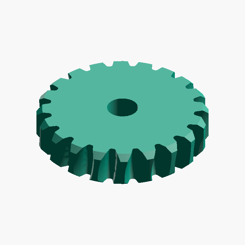
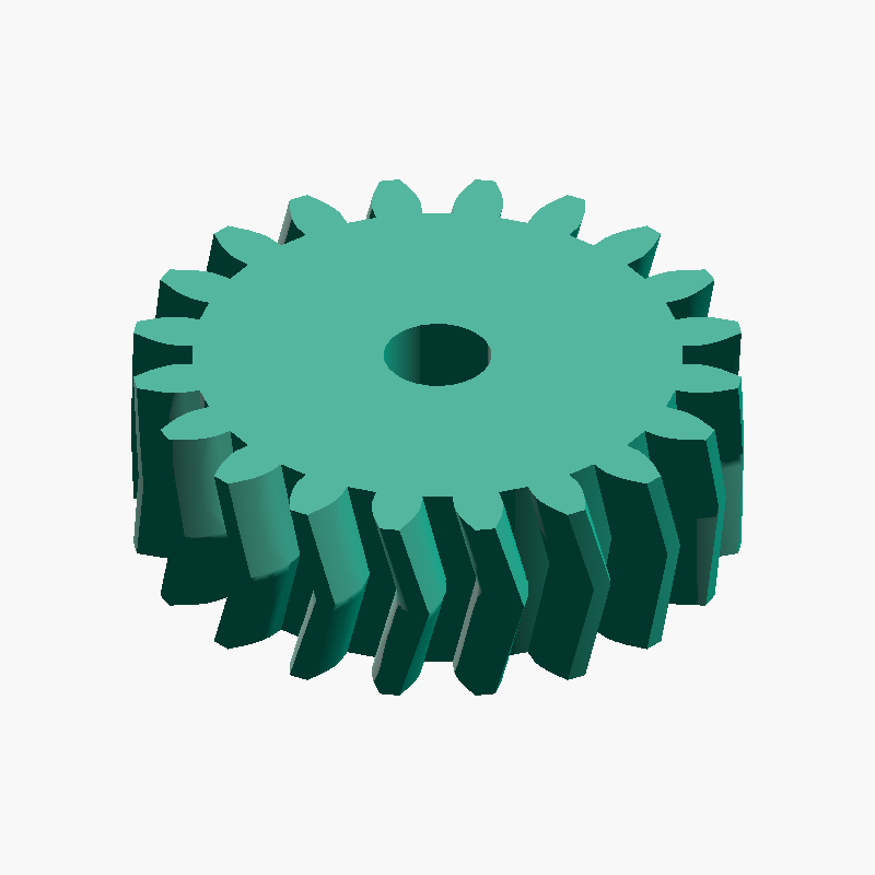
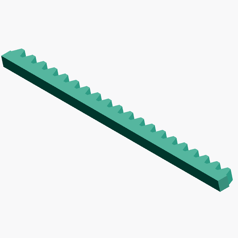
- Calcolatore rapporto di trasmissione Calcola il rapporto di trasmissione, la velocità di uscita e la coppia dal numero di denti motore e condotto (più stadi)
- Calcolatore denti e condizioni di montaggio di rotismi epicicloidali Calcola il numero di denti della corona e il rapporto di riduzione dai denti di solare e satelliti e dal numero di satelliti, e verifica le condizioni di montaggio e l'interferenza (con angoli di posizionamento CAD)
- Calcolatore distanza tra centri ingranaggi cilindrici Calcola distanza tra centri e dimensioni principali di ingranaggi cilindrici da modulo e due numeri di denti